Mitigating Technology Performance Risk in Biofuel Supply Chains: Strategies for Drug Development Research Stability
This article examines the critical challenge of technology performance risk within biofuel supply chains and its direct implications for the reliability of raw materials in biomedical and clinical research.
Mitigating Technology Performance Risk in Biofuel Supply Chains: Strategies for Drug Development Research Stability
Abstract
This article examines the critical challenge of technology performance risk within biofuel supply chains and its direct implications for the reliability of raw materials in biomedical and clinical research. Targeted at researchers, scientists, and drug development professionals, we explore the foundational sources of risk, present advanced modeling and mitigation methodologies, detail troubleshooting protocols for process optimization, and compare validation frameworks. The synthesis provides a strategic roadmap for securing robust, high-quality bio-derived solvents and feedstocks essential for reproducible scientific outcomes.
Understanding Technology Performance Risk: Defining Biofuel Supply Chain Vulnerabilities for Research
Defining Technology Performance Risk in the Biofuel Context
Technical Support Center
Troubleshooting Guides & FAQs
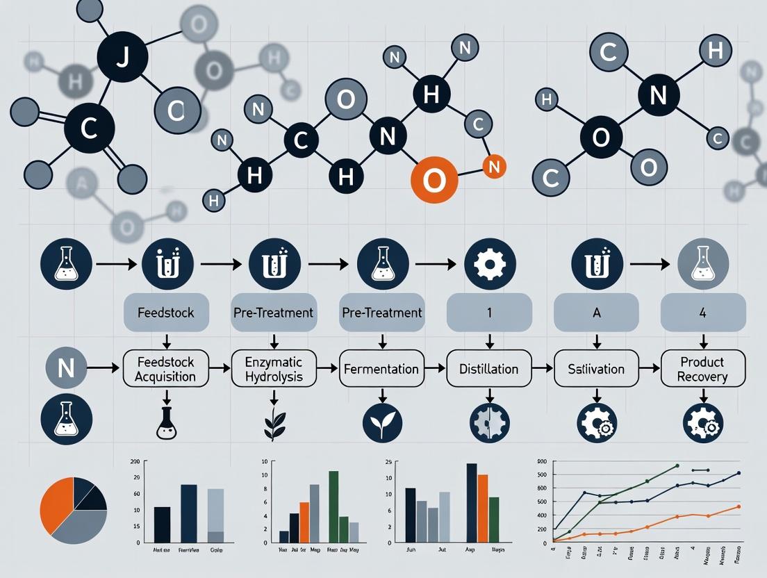
Feedstock Pre-Treatment & Hydrolysis
Q1: Our enzymatic hydrolysis of lignocellulosic biomass yields consistently lower sugar conversion than literature values. What are the primary factors to investigate?
A: Low sugar conversion is a critical technology performance risk. Investigate these factors systematically:
- Feedstock Variability: Particle size and lignin content vary between batches. Use a standardized milling/screening protocol.
- Inhibitor Presence: Pretreatment (e.g., dilute acid, steam explosion) generates furans and phenolics that inhibit enzymes. Assay for furfural, HMF, and phenolic acids.
- Enzyme Cocktail Efficiency: Commercial cellulase/hemicellulase blends may be suboptimal for your specific feedstock. Titrate enzyme loadings and consider supplementing with β-glucosidase.
- Process Parameters: Verify and tightly control pH (typically 4.8-5.0), temperature (50°C), and mixing shear force.
Experimental Protocol: Inhibitor Analysis via HPLC
- Method: High-Performance Liquid Chromatography (HPLC) with UV/RI detection.
- Column: Bio-Rad Aminex HPX-87H (for organic acids, alcohols, furans) or equivalent.
- Mobile Phase: 5 mM H₂SO₄, isocratic.
- Flow Rate: 0.6 mL/min.
- Temperature: 50°C.
- Detection: Refractive Index (RI) for sugars/alcohols; UV at 210/280 nm for acids/furans/phenolics.
- Sample Prep: Centrifuge hydrolysate, filter through 0.2 μm syringe filter, dilute as needed.
Q2: How can we rapidly assess feedstock composition to predict hydrolysis performance risk?
A: Implement the NREL/TP-510-42618 standard protocol for compositional analysis. Key metrics are listed in Table 1.
Table 1: Critical Feedstock Composition Metrics & Performance Risk Indicators
| Component | Target Range (Dry wt%) | Low Risk | High-Risk Indicator | Mitigation Action |
|---|---|---|---|---|
| Glucan | 35-50% | >40% | <35% | Blend feedstocks; optimize pretreatment. |
| Xylan | 15-25% | 20-25% | <15% | Adjust hemicellulase loading. |
| Acid-Insoluble Lignin | 10-20% | <15% | >25% | Consider alternative pretreatment (e.g., alkaline). |
| Ash | <5% | <3% | >10% | May inhibit catalysts; consider washing. |
| Extractives | <5% | <3% | >8% | Can foul equipment; pre-extract feedstock. |
Fermentation & Microbial Contamination
Q3: Our fermentation with S. cerevisiae shows sudden drops in ethanol productivity and elevated lactate. Is this metabolic shift or contamination?
A: Elevated lactate strongly indicates bacterial contamination (e.g., Lactobacillus). This is a severe operational risk.
Experimental Protocol: Contamination Diagnostic
- Microscopy: Perform Gram staining on broth sample. Look for rod-shaped Gram-positive bacteria alongside yeast cells.
- Selective Plating: Plate serial dilutions on MRS agar (for Lactobacillus) and YPD agar with cycloheximide (for yeast). Incubate anaerobically (MRS) and aerobically (YPD). Compare colony counts.
- PCR Assay: Use universal 16S rRNA primers (27F/1492R) on broth DNA. If positive, sequence to identify contaminant.
Q4: What are best practices to mitigate fermentation contamination risk in a pilot-scale bioreactor?
A:
- Sterilization: Validate steam-in-place (SIP) cycles for all lines and the vessel. Use biological indicators (e.g., Bacillus stearothermophilus spore strips).
- Inoculum Purity: Maintain sterile, master cell banks. Use pre-culture media with antibiotics (e.g., kanamycin) if the production strain is resistant.
- Process Control: Maintain a slight positive pressure in the reactor headspace with sterile air/N₂.
- Antimicrobial Agents: For non-recombinant yeast, consider adding 2-4 ppm of hop acids (isohumulones), which are effective against many Gram-positive bacteria.
Catalytic Upgrading & Catalyst Deactivation
Q5: Our hydrodeoxygenation (HDO) catalyst shows rapid deactivation (<50 hours) when upgrading bio-oil to hydrocarbons. What are the likely mechanisms?
A: Catalyst deactivation is a major technology performance risk. Likely mechanisms are fouling (coke), poisoning, and sintering.
Experimental Protocol: Post-Mortem Catalyst Analysis
- Thermogravimetric Analysis (TGA): Measure weight loss in air up to 800°C to quantify carbonaceous coke deposit.
- Temperature-Programmed Oxidation (TPO): Profile CO₂ evolution to determine coke reactivity/types.
- Inductively Coupled Plasma (ICP): Analyze spent catalyst for metal impurities (e.g., K, Na, Ca, P) leached from biomass.
- Physisorption/BET: Measure surface area loss to assess pore blocking/sintering.
- X-ray Diffraction (XRD): Check for changes in active metal crystallite size (sintering) or phase changes.
Table 2: Common Catalyst Deactivation Mechanisms in Bio-Oil HDO
| Mechanism | Primary Evidence | Common Cause in Bio-Oil | Potential Mitigation |
|---|---|---|---|
| Coking/Fouling | High C content (TGA), Pore volume loss (BET) | Polymerization of unsaturated/oxygenates | Lower T, increase H₂ pressure, use milder HDO steps. |
| Poisoning | Detection of K, Na, S, P on surface (ICP/MS) | Alkali/alkaline earth metals, biomass inorganics | Strict feedstock filtration/demineralization. |
| Sintering | Crystallite growth (XRD), Surface area loss (BET) | Local overheating, steam | Improve reactor temp control, add promoter (e.g., Sn). |
| Attrition | Fines in product, Pressure drop increase | Mechanical stress from mixing/flow | Use stronger catalyst supports (e.g., TiO₂, ZrO₂). |
Signaling Pathway & Experimental Workflow
Diagram Title: Biofuel Process Risk Cascade
Diagram Title: Troubleshooting Protocol Workflow
The Scientist's Toolkit: Research Reagent Solutions
Table 3: Essential Reagents for Biofuel Technology Risk Research
| Reagent/Material | Supplier Examples | Function in Risk Analysis |
|---|---|---|
| Commercial Cellulase Cocktail (e.g., CTec3, HTec3) | Novozymes, Dupont | Standardized enzyme blend for hydrolysis yield benchmarking. |
| NREL Standard Biomass (e.g., corn stover, poplar) | NIST/INREL | Control feedstock to isolate process variables from feedstock variability. |
| Anhydrous Sugar Standards (Glucose, Xylose, etc.) | Sigma-Aldrich, RESTEK | HPLC calibration for accurate yield quantification. |
| Inhibitor Standard Mix (Furfural, HMF, Acetic acid, etc.) | Sigma-Aldrich, Agilent | HPLC/GC calibration for inhibitor identification/quantification. |
| Selective Agar Media (MRS, YPD+Cycloheximide) | BD Difco, Thermo Fisher | Diagnostic for identifying microbial contamination types. |
| Model Bio-Oil Compounds (Guaiacol, Acetic acid) | TCI America, Alfa Aesar | Simpler substrates for controlled catalyst deactivation studies. |
| Catalyst Supports (γ-Al₂O₃, ZrO₂, Carbon) | Sigma-Aldrich, Alfa Aesar | Benchmarks for testing custom catalyst formulations. |
| DNA Extraction Kit (Microbial) | Qiagen, Mo Bio | For molecular identification of contaminants via 16S rRNA sequencing. |
Technical Support Center: Troubleshooting Bio-Conversion Experimental Processes
Welcome to the technical support center. This resource is designed within the context of broader research on addressing technology performance risk in biofuel supply chains. It provides targeted FAQs and protocols to help researchers mitigate key vulnerabilities related to feedstock inconsistency and process inefficiency.
FAQ & Troubleshooting Guide
Q1: Our lignocellulosic hydrolysis yields are inconsistent despite using a standard protocol. What could be causing this? A: Inconsistent yields are primarily due to feedstock compositional variability (e.g., lignin content, cellulose crystallinity). Pre-treatment efficiency is highly sensitive to this.
- Troubleshooting Steps:
- Characterize Feedstock: Perform immediate compositional analysis (see NREL/TP-510-42618) on the current and previous successful batches. Compare data.
- Adjust Pre-treatment: If lignin content is >5% higher than baseline, increase pre-treatment severity (e.g., temperature, acid concentration, or residence time) incrementally.
- Analyze Inhibitors: Test hydrolysate for elevated levels of inhibitors like furfural, HMF, or phenolic compounds, which suggest over-pre-treatment.
- Protocol - Feedstock Rapid Compositional Analysis:
- Mill feedstock to pass a 20-mesh screen.
- Perform a two-stage acid hydrolysis (72% H₂SO₄ at 30°C, then 4% H₂SO₄ at 121°C) to fractionate structural carbohydrates.
- Quantify sugars in the hydrolysate via HPLC (Aminex HPX-87P column) and acid-insoluble residue as lignin.
Q2: Our fermentation titers with engineered S. cerevisiae have dropped significantly, even with high sugar conversion. What should we check? A: This indicates a conversion inefficiency post-hydrolysis, likely due to microbial inhibition or metabolic stress.
- Troubleshooting Steps:
- Test Inhibitor Tolerance: Plate serial dilutions of your culture on standard media vs. media spiked with 50% process hydrolysate. Compare growth.
- Profile Metabolites: Use LC-MS to compare extracellular metabolite profiles (esp. organic acids, alcohols) between current and historical successful fermentations.
- Check Seed Train Vitality: Ensure inoculum is in mid-exponential phase (OD600 ~0.8-1.2) and has not undergone too many generations, which can lead to strain instability.
- Protocol - High-Throughput Inhibitor Tolerance Assay:
- In a 96-well plate, prepare a dilution series of your process hydrolysate in defined minimal media (0%, 10%, 25%, 50%, 75%).
- Inoculate each well with a standardized cell density (OD600 = 0.05) of your production strain.
- Monitor growth kinetics (OD600) for 48-72 hours using a plate reader. Calculate IC50 values.
Q3: How can we quickly assess the deactivation of our solid biocatalyst (e.g., immobilized enzyme) during repeated batches? A: Monitor both activity decay and physical integrity.
- Troubleshooting Steps:
- Measure Specific Activity: Compare the reaction rate (e.g., µmol product/min/g catalyst) of a fresh batch versus the used catalyst under identical, standardized conditions (pH, T, substrate conc.).
- Inspect for Leaching: Assay the reaction supernatant after catalyst removal for soluble protein/enzyme activity, indicating detachment.
- Analyze Physical Structure: Use SEM imaging to check for pore blockage, fragmentation, or biofilm formation on the catalyst surface.
- Protocol - Solid Catalyst Activity Retention Test:
- After each reuse cycle, wash the catalyst with buffer and conduct a standardized activity assay.
- Use 10 mg of catalyst, 5 mL of 100 mM substrate solution at optimal pH and temperature.
- Take samples at 1, 5, and 10 minutes, stop the reaction, and quantify product. Plot activity vs. cycle number.
Table 1: Impact of Feedstock Variability on Pre-treatment Output
| Feedstock Type | Lignin Content (%) | Cellulose Crystallinity Index | Optimal Pre-treatment Severity (Combined Factor, log R₀) | Glucose Yield (%) | Inhibitor Generation (g/L Furfural) |
|---|---|---|---|---|---|
| Corn Stover | 18.5 ± 1.2 | 48 ± 3 | 3.65 | 85.2 ± 2.1 | 0.8 ± 0.2 |
| Switchgrass | 22.1 ± 1.8 | 52 ± 4 | 3.85 | 78.5 ± 3.3 | 1.5 ± 0.3 |
| Poplar | 25.8 ± 2.1 | 55 ± 5 | 4.10 | 72.4 ± 4.0 | 2.4 ± 0.5 |
Table 2: Common Microbial Inhibitors and Mitigation Strategies
| Inhibitor Class | Example Compound | Critical Concentration (g/L) | Primary Effect on Microbe | Recommended Mitigation |
|---|---|---|---|---|
| Furan Derivatives | Furfural | >1.0 | DNA damage, enzyme inhibition | Overliming, activated carbon adsorption |
| Weak Acids | Acetic Acid | >3.0 | Internal pH collapse, uncoupler | pH control, strain engineering for tolerance |
| Phenolic Compounds | Vanillin | >0.5 | Membrane disruption | Laccase treatment, adaptive evolution |
The Scientist's Toolkit: Research Reagent Solutions
| Reagent / Material | Function & Application in Biofuel Research |
|---|---|
| Cellulase Cocktail (e.g., CTec2) | Multi-enzyme blend for saccharification of cellulose to glucose. Critical for standardized hydrolysis assays. |
| Aminex HPX-87H Column | HPLC column for separation and quantification of sugars, organic acids, and fermentation inhibitors. |
| YPD or Defined Minimal Media | For robust cultivation of yeast strains. Defined media is essential for metabolic studies and stress response assays. |
| Solid Acid Catalyst (e.g., Amberlyst-15) | Heterogeneous catalyst for esterification or hydrolysis reactions; used in lipid upgrading or inhibitor studies. |
| Microplate Reader with OD600 & Fluorescence | For high-throughput growth curves, viability assays (using resazurin), and promoter/reporter gene expression studies. |
Visualizations
Diagram 1: Feedstock to Biofuel Workflow with Key Vulnerabilities
Diagram 2: Inhibitor Impact on Microbial Cell
Technical Support Center
Troubleshooting Guide & FAQs
Q1: My cell viability assays show high, unexplained cytotoxicity in control groups when using fresh aliquots of molecular biology grade ethanol. What could be the cause? A: This is a critical issue often traced to solvent quality degradation or contamination. In biofuel supply chain research, ethanol purity is paramount. Impurities like aldehydes (acetaldehyde), organic acids, or high-peroxide solvents from autoxidation can introduce cytotoxic compounds.
- Actionable Protocol: Test solvent purity via GC-MS headspace analysis. As a rapid functional test, perform a sensitive cell viability assay (e.g., ATP-based luminescence) using a dilution series of your solvent against a fresh, certified ACS-grade benchmark.
- Quantitative Risk Data:
| Impurity in Ethanol | Typical Specification Limit (ppm) | Observed Cytotoxic Threshold in Cell Culture (ppm) | Common Source in Supply Chain |
|---|---|---|---|
| Acetaldehyde | ≤ 10 | ~5-10 | Incomplete synthesis or degradation |
| Methanol | ≤ 200 | ~1000-2000 | Feedstock impurity from biomass hydrolysis |
| Benzene | ≤ 1 | ~1-5 | Contamination during distribution or packaging |
| Water Content | ≤ 0.5% | N/A (context-dependent) | Absorption during transfer or storage |
Q2: My protein precipitation protocol with HPLC-grade acetone is yielding inconsistent recoveries. How do I troubleshoot this? A: Inconsistent recoveries frequently stem from solvent stabilizers or water content variance. Biofuel-derived acetone may have different stabilizer profiles than petrochemical sources.
- Actionable Protocol:
- Check the certificate of analysis (CoA) for the stabilizer (often BHT or cyclopentadiene) and water content.
- Evaporate a sample of the acetone under a gentle nitrogen stream and re-constitute in a stabilizer-free grade. Repeat the precipitation.
- For water content, use Karl Fischer titration. If >0.5%, dry over a molecular sieve (3Å) before use.
- Standardize your protocol: Always pre-chill acetone to -20°C and use a fixed sample-to-solvent ratio (e.g., 1:4 v/v) and incubation time (60 min at -20°C).
Q3: I suspect lot-to-lot variability in my bioreagent buffers is affecting enzyme kinetics in my biocatalyst assays. How can I validate this? A: This directly mirrors technology performance risks in scaling up biocatalytic processes for biofuels. Buffer salts and pH adjusters can contain metal contaminants that inhibit enzymes.
- Actionable Protocol: ICP-MS Analysis of Buffer Components.
- Prepare Samples: Dissolve 1g of each buffer salt lot (e.g., phosphate, Tris) in 50 mL of ultrapure water (18.2 MΩ·cm).
- Analysis: Use Inductively Coupled Plasma Mass Spectrometry (ICP-MS) to screen for transition metals (Ni, Cu, Fe, Co, Zn) at ppb levels.
- Functional Test: Perform a standard enzyme activity assay (e.g., for a dehydrogenase or cellulase) using buffers made from the different lots. Compare initial reaction velocities (V0).
- The Scientist's Toolkit: Research Reagent Solutions
| Item | Function in Troubleshooting |
|---|---|
| Karl Fischer Titrator | Precisely measures trace water content in organic solvents. |
| GC-MS System | Identifies and quantifies volatile organic impurities in solvents. |
| ICP-MS | Detects ultra-trace metal contaminants in salts and water. |
| ACS-Grade & HPLC-Grade Solvents | Benchmarked materials with stringent purity specifications. |
| Molecular Sieves (3Å, 4Å) | For on-site drying of solvents like acetone, acetonitrile, and DMSO. |
| In-line Solvent Filters (0.2 µm PTFE) | Removes particulates and microbial contamination from bulk dispensers. |
Experimental Protocol: Validating Solvent Purity via Peroxide Test in Tetrahydrofuran (THF) Background: THF, used in membrane lipid extraction, forms explosive peroxides upon aging. Biofuel supply chains using furanic compounds may encounter similar instability.
- Reagent: Prepare test strips using potassium iodide/starch paper or use a commercial peroxide test kit.
- Method: In a fume hood, dip the test strip into the THF sample for 1 second. Remove and observe immediately.
- Analysis: Compare the color change to the provided scale. Peroxide levels >50 ppm are considered hazardous and the solvent must be deactivated and disposed of properly. Do not use.
- Prevention: Always purchase THF with BHT stabilizer, store under inert gas (argon), and use within 6 months of opening.
Visualizations
Solvent Quality Risk Pathway in Supply Chain
Troubleshooting Workflow for Reagent-Driven Issues
Technical Support Center
Troubleshooting Guide: Common Biofuel Inconsistency Issues in Lab Research
FAQ 1: Why are my cell culture viability assays showing high variability after switching to a new batch of algal biofuel-derived solvent?
- Issue: Biofuel feedstocks (e.g., algal oil) vary seasonally and by processing method, leading to inconsistent trace contaminant profiles (pesticides, heavy metals, organic acids) that are cytotoxic.
- Solution: Implement a pre-screening protocol for each new solvent batch. Use Gas Chromatography-Mass Spectrometry (GC-MS) to profile contaminants. Pass the solvent through a customized cleanup column (e.g., silica gel or activated carbon) before use in sensitive assays. Establish acceptance criteria based on historical performance data of batches associated with successful experiments.
FAQ 2: My enzymatic biodiesel conversion yields have dropped significantly despite using the same protocol. What could be wrong?
- Issue: Inconsistent purity and composition of biofuel feedstocks (e.g., waste cooking oil) can introduce impurities (water, free fatty acids, peroxides) that deactivate or inhibit enzymatic catalysts (lipases).
- Solution: Quantify key impurities in the incoming feedstock. See Table 1 for thresholds. Pre-treat the feedstock to standardize it: use molecular sieves to remove water, perform acid esterification to neutralize high FFA content before the main enzymatic transesterification step.
FAQ 3: How can I prevent fouling and erratic results in my high-throughput catalyst screening system when testing bio-oils?
- Issue: Pyrolysis bio-oils are chemically complex and unstable, forming gums and solids that clog microfluidic channels or deposit on catalyst surfaces, leading to inconsistent activity measurements.
- Solution: Implement an inline filtration (0.2 µm) and a standardized "aging" protocol for the bio-oil sample prior to testing. Use a solvent carrier stream (e.g., tetrahydrofuran) to improve flow characteristics. Clean the system with a standardized solvent flush (acetone → ethanol → hexane) between each sample run.
FAQ 4: Why does my fermentation titers drop when using hydrotreated vegetable oil (HVO) as a carbon source compared to pure glucose?
- Issue: HVOs, while chemically similar to alkanes, can have inconsistent nutrient content (lack of co-factors, sterols) essential for microbial growth, leading to unreliable metabolic activity.
- Solution: Supplement the HVO-based fermentation medium with a defined cocktail of micronutrients (see Table 2: Research Reagent Solutions). Perform a growth curve assay with each new HVO batch to calibrate the supplementation needs.
Data Presentation
Table 1: Critical Impurity Thresholds in Biodiesel Feedstocks for Consistent Enzymatic Conversion
| Impurity | Acceptable Threshold for Lipase Activity | Standard Test Method | Recommended Pretreatment if Exceeded |
|---|---|---|---|
| Water Content | < 0.05% w/w | ASTM D6304 | Drying with 3Å molecular sieves |
| Free Fatty Acids (FFA) | < 2% w/w | AOCS Ca 5a-40 | Acid-catalyzed esterification |
| Peroxide Value (PV) | < 5 meq/kg | AOCS Cd 8b-90 | Reduction with sodium sulfite |
| Phosphorus Content | < 10 ppm | EN 14107 | Acid degumming |
Table 2: Research Reagent Solutions for Microbial Cultivation on Hydrotreated Biofuels
| Reagent | Function | Typical Concentration in Medium |
|---|---|---|
| Methyltricaprylylammonium Chloride | Increases bioavailability of hydrophobic alkane substrates. | 0.01% v/v |
| Ergosterol | Essential membrane component for many yeasts when grown on non-fermentable carbon. | 20 mg/L |
| Tween 80 | Non-ionic surfactant to emulsify fuel and improve uptake. | 0.1% v/v |
| Trace Metal Solution (e.g., Cu, Mn, Co, Mo) | Provides micronutrients absent in purified hydrocarbon streams. | 1 mL/L |
Experimental Protocols
Protocol 1: Standardized Pre-Treatment of Waste Cooking Oil for Enzymatic Biodiesel Synthesis
- Characterization: Determine water (Karl Fischer titration) and FFA (titration) content of the raw oil.
- Dehydration: If water >0.05%, heat oil to 110°C while stirring under vacuum (100 mbar) for 30 minutes. Alternatively, add 5% w/w of pre-activated 3Å molecular sieves and stir for 24 hours at room temperature.
- Acid Esterification (if FFA >2%): For every 100g of oil, mix with 20g of methanol and 1g of concentrated sulfuric acid (H₂SO₄). React at 60°C with stirring (600 rpm) for 2 hours. Transfer to a separatory funnel, allow phases to separate, and discard the lower glycerol/acid layer.
- Neutralization & Drying: Wash the oil layer with warm (50°C) deionized water until pH neutral. Dry the washed oil over anhydrous sodium sulfate (Na₂SO₄) for 12 hours, then filter.
- Quality Control: Re-analyze water and FFA content. Proceed to enzymatic transesterification only if within thresholds specified in Table 1.
Protocol 2: Cytotoxicity Screening of Biofuel-Derived Solvent Batches
- Sample Preparation: Aliquot 10 mL of the suspect biofuel solvent (e.g., bio-based acetone). Evaporate to dryness under a gentle nitrogen stream. Reconstitute the non-volatile residue in 1 mL of DMSO.
- Cell Exposure: Plate HEK-293 or relevant cell line in a 96-well plate at 10,000 cells/well. Incubate for 24 hours. Prepare a dilution series of the reconstituted residue (e.g., 0.1%, 0.5%, 1% v/v in culture medium). Expose cells to these dilutions for 48 hours.
- Viability Assay: Perform an MTT or resazurin assay according to manufacturer instructions. Measure absorbance/fluorescence.
- Analysis: Compare dose-response curves against a historical solvent batch known to support normal cell growth. A new batch causing >20% reduction in viability at 0.5% concentration should be flagged for further purification.
Mandatory Visualizations
Biofuel Inconsistency Impact & Mitigation Pathway
Feedstock Quality Control Decision Workflow
Technical Support Center
FAQs & Troubleshooting Guide for Biofuel Supply Chain Digital Twin Experiments
Q1: My biomass feedstock quality model in the digital twin is producing inaccurate yield predictions. What calibration steps should I follow? A: Inaccurate feedstock models are often due to misaligned data granularity. Follow this protocol:
- Data Synchronization: Ensure the physical sensor data (e.g., moisture, lignin content from NIR spectroscopy) matches the temporal resolution of the twin's simulation clock. If sensors log hourly, but the twin updates every 15 minutes, implement a data interpolation or averaging protocol.
- Parameter Calibration: Run a batch of 10-15 controlled pretreatment experiments with varying feedstock batches. Use the results to calibrate the kinetic parameters in the twin's reaction model via a gradient descent algorithm.
- Validation: Reserve 20% of the experimental data for validation. The model's Mean Absolute Percentage Error (MAPE) should be below 8% for the validation set to be considered calibrated.
Q2: The AI module for predicting enzymatic hydrolysis failure is generating too many false-positive alerts. How can I refine it? A: This indicates a class imbalance or noisy training data. Implement this methodology:
- Data Curation: Re-label your historical failure event data. A "true failure" is defined as a conversion rate drop below 65% of the projected yield within a 4-hour window. Other anomalies should be labeled as "minor fluctuations."
- Algorithm Tuning: Switch from a standard Random Forest classifier to a Gradient Boosting model (XGBoost) and adjust the classification threshold. Use a confusion matrix from your test set to find the optimal threshold that balances precision and recall.
- Feature Engineering: Add a rolling standard deviation (window=12 time steps) of the bioreactor's temperature and pH as new input features to help the AI distinguish between noise and a genuine trend.
Q3: How do I integrate real-time logistics (transportation delays) into my supply chain risk model? A: Use a hybrid simulation-AI approach.
- Protocol: Establish an API connection between your digital twin platform and a live traffic/weather data feed (e.g., Google Maps API, NOAA API).
- Model Update: Create a discrete event simulation module for transportation. The AI component (a recurrent neural network) continuously ingests the live feed to predict delay probabilities, which then update the simulation parameters.
- Trigger: Set a rule that if the predicted delay exceeds 8 hours, the twin automatically initiates a "risk mitigation" workflow, suggesting alternative storage or rerouting.
Quantitative Data Summary
Table 1: Performance Metrics of AI Models for Preprocessing Fault Detection
| AI Model | Average Precision | Recall | False Positive Rate | Training Data Required (hours) |
|---|---|---|---|---|
| Logistic Regression | 0.72 | 0.65 | 0.18 | 500 |
| Random Forest | 0.89 | 0.82 | 0.09 | 750 |
| XGBoost (Optimized) | 0.94 | 0.88 | 0.05 | 1000 |
| LSTM Neural Network | 0.91 | 0.90 | 0.11 | 2000 |
Table 2: Impact of Digital Twin Calibration on Predictive Accuracy
| Supply Chain Stage | Prediction Error (Uncalibrated) | Prediction Error (Calibrated) | Key Calibration Parameter |
|---|---|---|---|
| Feedstock Preprocessing | 22% | 7% | Cellulose Crystallinity Index |
| Enzymatic Hydrolysis | 18% | 5% | Enzyme Inhibition Constant (Ki) |
| Fermentation & Distillation | 15% | 6% | Yeast Ethanol Tolerance (g/L) |
| Logistics & Storage | 30% | 12% | Feedstock Degradation Rate |
Experimental Protocol: Validating a Digital Twin's Fermentation Inhibition Warning Objective: To physically verify an AI-generated prediction of microbial inhibition due to feedstock-derived inhibitors. Methodology:
- Trigger: When the digital twin's AI module predicts a >40% probability of inhibition in a fermentation batch, flag the corresponding physical feedstock batch.
- Sampling: Aseptically withdraw 3 x 100mL samples from the flagged fermenter at T=0h, 12h, and 24h.
- Analysis:
- HPLC: Quantify concentrations of target inhibitors (e.g., furfural, HMF, acetic acid).
- Viability Staining: Use fluorescent dyes (e.g., propidium iodide, SYTO 9) in a flow cytometer to determine live/dead cell ratio.
- qPCR: Measure expression levels of key stress response genes (e.g., HSP12, ADH2).
- Correlation: Statistically correlate inhibitor levels and viability metrics with the AI's predicted probability and the digital twin's simulated metabolite profiles.
Visualizations
Title: Digital Twin & AI Risk Identification Workflow
Title: Experimental Protocol for Validating AI Predictions
The Scientist's Toolkit: Research Reagent Solutions
Table: Key Reagents for Biofuel Process Risk Experimentation
| Item | Function in Risk Identification Experiments |
|---|---|
| Near-Infrared (NIR) Spectrometer Probe | Provides real-time, non-destructive analysis of feedstock composition (cellulose, hemicellulose, moisture), critical for digital twin input calibration. |
| Inhibitor Standard Mix (Furfural, HMF, Acetic Acid) | HPLC standard for quantifying microbial fermentation inhibitors derived from biomass pretreatment, enabling validation of AI toxicity predictions. |
| LIVE/DEAD BacLight Bacterial Viability Kit | Fluorescent staining assay to quantify live vs. dead cell ratios in fermentation broths, providing ground-truth data for AI-based health forecasts. |
| qPCR Assay for Yeast Stress Genes (e.g., HSP12) | Measures molecular-level stress response in real-time, used to correlate digital twin metabolic simulations with physical cellular states. |
| IoT-Enabled pH/Temperature Loggers | Provides continuous, time-stamped environmental data streams essential for synchronizing the physical process with its digital twin. |
| Enzymatic Hydrolysis Assay Kit (DNS Method) | Bench-scale kit for rapid quantification of reducing sugars, used for frequent calibration of the digital twin's conversion efficiency models. |
Advanced Modeling and Mitigation: Applying Risk Quantification Tools to Secure Bio-Supplies
Quantitative Risk Assessment (QRA) Frameworks for Biofuel Processes
Technical Support Center: Troubleshooting QRA for Biofuel Experiments
Frequently Asked Questions (FAQs)
Q1: During QRA modeling for a novel lignocellulosic hydrolysis step, my risk probability calculations are yielding inconsistent results across simulation runs. What could be the cause? A: Inconsistent results often stem from poorly defined probability distributions for input variables. Ensure that for key parameters like enzyme activity (IU/g), inhibitor concentration (g/L), and reaction temperature (°C), you have defined the correct statistical distribution (e.g., Normal, Log-normal, Uniform) based on empirical data. Using a default uniform distribution without experimental justification leads to output variance. Re-calibrate your model using the protocol for "Parameter Distribution Fitting" below.
Q2: How do I quantitatively integrate catalyst deactivation data from lab-scale experiments into a full-scale process QRA for biodiesel production? A: Catalyst deactivation rate is a critical performance risk. You must scale the deactivation function. Use lab-scale time-on-stream (TOS) data to fit a decay model (e.g., exponential: k_d = Aexp(-Ea/RT)*). In your QRA, treat the pre-exponential factor (A) and activation energy (Ea) as uncertain variables with distributions defined by your lab data's confidence intervals. Then, run Monte Carlo simulations to propagate this uncertainty to catalyst replacement cost and downtime risk at scale.
Q3: My consequence analysis for a fermentation tank overpressure scenario seems underestimated compared to historical incident data. Which parameters are most sensitive? A: The top sensitive parameters are typically: 1) Failure Rate of Pressure Relief Valves (PRVs): Use industry benchmark data (e.g., OREDA, CCPS) instead of manufacturer specs. 2) Vapor Cloud Composition: Ensure your model uses the actual composition of off-gas (CO2, H2, ethanol) not just pure CO2. 3) Ignition Probability: For biofuel processes, this is often higher due to combustible dusts; adjust location-specific probabilities. Re-run your event tree with these updated parameters.
Q4: When assessing feedstock variability risk, what are the key quantitative metrics to link feedstock properties to final yield? A: The key is to establish Transfer Functions. Create correlations such as:
- Cellulose Crystallinity Index (%) → Glucose Yield (% theoretical)
- Ash Content (% dry basis) → Catalyst Poisoning Rate (%/batch)
- Moisture Variability (SD %) → Pretreatment Energy Consumption (GJ/ton) Perform multivariate regression on your experimental data to define these functions, then use them as risk models in your QRA to translate feedstock specs into financial and yield volatility.
Experimental Protocols for QRA Data Generation
Protocol 1: Determining Probability Distribution for Enzyme Hydrolysis Yield Objective: Generate the data required to define a probability density function (PDF) for glucose yield in a probabilistic QRA model. Methodology:
- Design of Experiments (DoE): Set up a central composite design (CCD) with three key variables: solid loading (15-25% w/v), enzyme dosage (10-30 mg protein/g glucan), and time (48-72h). Use 5 levels for each variable.
- Replication: Execute each experimental run in triplicate (n=3) to capture inherent process variability.
- Analysis: Quantify glucose yield via HPLC. For each run condition, calculate the mean and standard deviation of yield.
- Distribution Fitting: Pool all replicate data (e.g., 90 data points). Use statistical software (e.g., R, @Risk) to fit Normal, Log-normal, and Weibull distributions. Perform a Kolmogorov-Smirnov test to select the best-fitting distribution.
- Output: The fitted distribution (e.g., Yield ~ N(μ=85%, σ=3.2%)) is used directly as an input variable in the QRA Monte Carlo simulation.
Protocol 2: Failure Mode Testing for Solid-Liquid Separation Unit Objective: Obtain quantitative data on failure rates (probability) and severity (time delay) for a filter press in a pilot-scale algal lipid extraction process. Methodology:
- Define Failure Modes: Primary modes: (a) Cake blow-through (due to incorrect particle size), (b) Cloth blinding (due to polymer overdose), (c) Cycle overrun (due to pump decay).
- Accelerated Testing: Under controlled conditions, induce failures. E.g., for (a), systematically vary algal cell disruptor energy (kJ/L) to alter particle size distribution and record the pressure (psi) at which blow-through occurs. Repeat 30 times.
- Data Recording: For each test, record: time to failure (T), process parameter at failure (P), and downtime for remediation (D).
- Data Analysis: Calculate probability as (# of failures / # of trials) for each mode. Fit time-to-failure data to an exponential distribution to derive a failure rate (λ, failures/operating hour). Severity is defined as the distribution of downtime (D).
- QRA Integration: These quantified λ and D distributions populate the fault tree and LOPA (Layer of Protection Analysis) for this equipment item.
Table 1: Typical Failure Rate Data for Key Biofuel Process Units
| Process Unit | Failure Mode | Probability (per demand or per year) | Data Source |
|---|---|---|---|
| Anaerobic Digester | Feedstock Pump Seal Leak | 2.1e-3 / year | OREDA (2023) |
| Transesterification Reactor | Methanol Feed Valve Fails Closed | 1.0e-4 / demand | CCPS PRA Guidelines |
| Centrifuge (Algal Dewatering) | Bowl Imbalance Shutdown | 5.6e-2 / year | Biofuel Plant Op Data (2022-24) |
| Pyrolysis Reactor | Coke Formation > Spec Limit | 1.2 / year | Industry Benchmarking Study |
Table 2: QRA Output for Fischer-Tropsch Biofuel Process: Top 5 Risk Contributors
| Risk Scenario | Frequency (events/year) | Consequence (Million USD) | Risk (USD/year) | % of Total Risk |
|---|---|---|---|---|
| Syngas Compressor Explosion | 1.2e-4 | 45.2 | 5,424 | 31% |
| Catalyst Sintering (Yield Loss) | 1.0e+0 | 0.85 | 850 | 18% |
| H₂ Supply Interruption (>4h) | 2.5e-1 | 2.1 | 525 | 11% |
| Wax Product Solidification in Line | 5.0e-1 | 0.65 | 325 | 7% |
| Feedstock Switch (Quality Issue) | 1.0e+0 | 0.28 | 280 | 6% |
Visualizations
QRA Workflow for a Biofuel Process Unit
Fault Tree for Fermentation Runaway Scenario
The Scientist's Toolkit: Research Reagent Solutions
Table 3: Essential Materials for QRA-Ready Biofuel Experiments
| Item | Function in QRA Context | Example Product/Supplier |
|---|---|---|
| Process Analytics (PTR-MS) | Provides real-time, high-resolution volatile organic compound (VOC) data for emission event frequency and consequence modeling. | Ionicon PTR-TOF 6000 X2 |
| Bench-Scale Continuous Reactor System | Enables accelerated lifetime and failure testing under controlled upsets to generate quantitative failure rate data (λ). | Ammarks Continuous Flow System |
| Catalyst Characterization Suite (BET, TPD, XRD) | Quantifies catalyst degradation rates (sintering, poisoning) to model performance decay risk over time. | Micromeritics 3Flex, Anton Paar XRD |
| Statistical Software with Monte Carlo Package | Performs probabilistic risk calculations, sensitivity analysis, and distribution fitting for QRA models. | Palisade @Risk, R (riskassessment package) |
| High-Throughput Saccharification Assay Kits | Rapidly generates large datasets on feedstock variability (100s of samples) to define input uncertainty for QRA. | Megazyme BIOCHAIN Lignocellulose Kit |
Application of Monte Carlo Simulations for Yield and Purity Forecasting
Technical Support Center
Frequently Asked Questions (FAQs) & Troubleshooting
Q1: My Monte Carlo simulation for biofuel yield prediction shows improbably high or low extreme values (outliers). What could be the cause and how can I fix it? A: This typically indicates an issue with the input probability distributions for key process parameters (e.g., enzyme activity, feedstock sugar content).
- Troubleshooting Steps:
- Validate Input Data: Re-examine the experimental data used to fit your input distributions. Ensure there are no measurement or data entry errors.
- Check Distribution Fit: Use statistical goodness-of-fit tests (e.g., Kolmogorov-Smirnov, Anderson-Darling) to confirm the chosen distribution (Normal, Lognormal, Beta, Triangular) accurately represents your empirical data. A poor fit will generate unrealistic random samples.
- Review Physical Limits: Implement distribution truncation. For example, if enzyme concentration cannot be negative, truncate the Normal distribution at zero. Define realistic min/max bounds for all variables.
- Inspect Correlations: Confirm that any defined correlations between input variables (e.g., between temperature and reaction rate) are physiologically plausible and correctly coded in the simulation model.
Q2: How do I determine the correct number of simulation iterations (runs) for reliable forecasting of product purity? A: The required number of iterations depends on the desired precision and model complexity.
- Troubleshooting Guide:
- Perform a Convergence Analysis: Run the simulation in batches (e.g., 1,000, 5,000, 10,000, 50,000 iterations). After each batch, calculate the mean and standard deviation of your key output (e.g., purity percentage).
- Monitor Stability: Plot the output statistics against the number of iterations. The point where the mean and standard deviation stabilize (show minimal fluctuation) indicates a sufficient number of runs.
- Rule of Thumb: For a preliminary biofuel process screening, 10,000 iterations may suffice. For robust quantification of low-probability risk events (e.g., purity falling below a critical threshold), 100,000+ iterations are often necessary. Refer to the convergence data below.
Table 1: Example Convergence Analysis for Purity Forecast
| Number of Iterations | Forecast Mean Purity (%) | Standard Deviation (%) | Change in Mean from Previous Batch |
|---|---|---|---|
| 1,000 | 92.5 | 3.2 | - |
| 5,000 | 93.1 | 3.05 | +0.6 |
| 10,000 | 93.0 | 3.08 | -0.1 |
| 50,000 | 93.02 | 3.07 | +0.02 |
Q3: My simulation results do not align with my small-scale laboratory experimental results. How should I proceed? A: This discrepancy is a key risk assessment outcome. Systematic investigation is required.
- Action Protocol:
- Audit Model Assumptions: Critically review all transfer functions and equations in your simulation that link inputs (e.g., feedstock variability) to outputs (yield/purity). Are scaling effects (from lab to pilot/commercial) accurately captured?
- Calibrate with Bayesian Inference: Use your lab data as a prior distribution to update and calibrate the simulation model. This formally integrates empirical evidence into the forecast.
- Identify Hidden Variables: The discrepancy may reveal an uncontrolled critical process parameter (CPP) in the lab (e.g., trace inhibitor presence) not included in the model. Design new, targeted experiments to identify it.
- Document the Gap: This mismatch is valuable data for your thesis on technology performance risk, highlighting a specific scale-up uncertainty for the biofuel supply chain.
Experimental Protocol: Integrating Monte Carlo Simulation with Laboratory Data
Title: Protocol for Calibrating a Hydrolysis Yield Forecast Model Using Experimental Data.
Objective: To refine a Monte Carlo simulation model of lignocellulosic sugar yield by updating input parameter distributions with latest experimental results.
Materials & Method:
- Baseline Simulation: Establish a pre-calibration simulation model with defined stochastic inputs (e.g., feedstock cellulose content ~N(45, 5)%, enzyme loading ~Triang(10, 15, 20) mg/g).
- Laboratory Experiment: Perform 30 independent hydrolysis experiments under the defined process range. Precisely measure the resulting sugar yield for each run.
- Statistical Comparison: Use the
scipy.statspackage in Python to compare the distribution of the simulated output to the distribution of the experimental output using a two-sample Kolmogorov-Smirnov test. - Model Calibration: Implement a simple Markov Chain Monte Carlo (MCMC) sampling routine (e.g., using
PyMC3orStan) to adjust the mean and variance of key input distributions so that the simulation output distribution better matches the experimental data. - Validation: Run the calibrated simulation and compare its output to a hold-out set of experimental data not used in calibration.
The Scientist's Toolkit: Research Reagent Solutions
Table 2: Key Reagents & Materials for Yield/Purity Analysis Experiments
| Item Name | Function in Experiment |
|---|---|
| Lignocellulolytic Enzyme Cocktail (e.g., Cellic CTec3) | Hydrolyzes cellulose and hemicellulose in feedstock into fermentable sugars. Key stochastic variable in yield simulations. |
| High-Performance Liquid Chromatography (HPLC) System with Refractive Index Detector | Quantifies sugar monomers (glucose, xylose) and by-products (inhibitors) for precise yield and purity calculation from experimental runs. |
| Certified Reference Standards (Glucose, Xylose, Furfural, HMF) | Essential for calibrating the HPLC to generate accurate, quantitative data for model input and validation. |
| Process Modeling Software (Python with NumPy/SciPy/PyMC3, @RISK, Crystal Ball) | Platform for building, running, and analyzing Monte Carlo simulations, including statistical fitting and advanced calibration. |
| Defined Composition Feedstock Slurry | Standardized substrate (e.g., pretreated corn stover) with characterized compositional variability, used to define input distributions for the simulation. |
Visualizations
Title: Monte Carlo Yield Forecasting Workflow
Title: Key Risk Factors in Biofuel Yield Pathway
Supply Chain Mapping and Critical Control Point (CCP) Analysis
Technical Support Center
Troubleshooting Guides & FAQs
Q1: Our biomass feedstock sensor network is reporting inconsistent compositional data (e.g., lignin, cellulose content), compromising our upstream supply mapping. What are the primary troubleshooting steps?
A: Inconsistent sensor data typically stems from calibration drift, particulate contamination, or moisture interference.
- Protocol 1 - On-site Calibration Verification:
- Take three physical samples from the same biomass lot at the sensor intake point.
- Perform standard lab-based NIR spectroscopy or wet chemistry analysis (e.g., NREL/TP-510-42618) to establish benchmark values.
- Compare sensor outputs for the same lot against lab results. A deviation >5% requires recalibration.
- Execute the sensor's built-in recalibration routine using provided standard reference materials.
- Protocol 2 - Contamination Check: Power down and isolate the sensor. Visually inspect the optical window or probe for residue. Clean using manufacturer-specified solvent (e.g., anhydrous ethanol). Perform a post-cleaning baseline measurement in a clean air environment before redeployment.
Q2: During enzymatic hydrolysis, we observe variable sugar yield despite controlled bioreactor conditions, indicating a potential CCP failure. How do we systematically isolate the cause?
A: Variable yield at this CCP often points to feedstock variability or enzyme activity issues. Follow this isolation protocol:
- Test 1 - Feedstock Consistency: Analyze the current and three previous feedstock batches for particle size distribution (Sieve analysis, ASTM E11) and crystallinity index (via XRD). Tabulate results.
- Test 2 - Enzyme Activity Assay: Perform a filter paper unit (FPU) assay (Adney & Baker, 2008) on the enzyme cocktail from the current production run versus a new, reference aliquot. Activity should be within 10%.
- Cross-Reference: If feedstock is consistent but enzyme activity is low, the CCP is enzyme storage/supply. If feedstock is variable, the CCP is pre-processing.
Q3: The real-time viscosity monitoring system in our lipid transesterification reactor is lagging, risking delayed correction and off-spec biodiesel. What immediate actions should be taken?
A: System lag is a critical control failure. Take these immediate steps:
- Manual Override & Sampling: Switch control to manual and maintain current parameters. Extract a 100mL sample aseptically.
- Immediate Offline Test: Perform a rapid viscosity measurement using a calibrated bench-top viscometer (e.g., Brookfield) at standard shear rate and temperature (e.g., 40°C).
- Compare & Adjust: Compare the offline result to the lagging real-time readout. Use the offline value for immediate process adjustment.
- Diagnostic: Check the in-line viscometer's shear element for fouling and the data transmission line for latency. Clean or replace as necessary.
Data Tables
Table 1: Common Sensor Deviations & Corrective Actions in Biomass Pre-Processing
| Sensor Type | Measured Parameter | Acceptable Range | Typical Deviation Cause | Corrective Action |
|---|---|---|---|---|
| NIR Spectrometer | Cellulose Content | ±2.5% of lab value | Moisture film on lens | Dry purge, clean with lint-free cloth |
| RFID Scanner | Batch ID Traceability | 100% read rate | Physical damage, radio interference | Replace tag/antenna, shield from motors |
| Mass Flow Meter | Feedstock Input (kg/hr) | ±1.5% of setpoint | Pipe vibration, build-up | Re-tighten mounts, inspect for blockages |
Table 2: Critical Control Point (CCP) Performance Metrics in Pilot-Scale Hydroprocessing
| CCP Name | Control Parameter | Target Value | Control Limits | Monitoring Frequency | Corrective Action |
|---|---|---|---|---|---|
| Hydrotreater Inlet | Temperature | 345°C | 340-350°C | Continuous (RT) | Adjust heat exchanger bypass |
| Catalyst Bed | Pressure Drop | 0.5 bar/m | 0.4-0.6 bar/m | Hourly | Check for feed particulates |
| Product Separator | Water Content | <0.5% vol | <0.8% vol | Per 4-hour batch | Increase coalescer setting |
Experimental Protocols
Protocol: Mapping Feedstock Variability Using Geospatial & Compositional Data Objective: To quantitatively map variability in biomass feedstock as a source of technology performance risk. Methodology:
- Sample Collection: Geotag and collect biomass samples (e.g., switchgrass bales) from 50 points across the supply region using a stratified random grid.
- Compositional Analysis: For each sample, determine glucan, xylan, and lignin content using a two-stage acid hydrolysis according to NREL Laboratory Analytical Procedure (LAP) "Determination of Structural Carbohydrates and Lignin in Biomass".
- Data Integration: Use GIS software (e.g., QGIS) to create layered maps plotting geographical coordinates against compositional data (e.g., a color-gradient map for lignin content).
- Statistical Analysis: Calculate coefficient of variation (CV) for each component across the region. A CV >15% for a key component flags a high-variability zone requiring a separate CCP.
Protocol: Stress-Testing a Blockchain-Based Traceability Node Objective: To evaluate the failure risk of a digital traceability system, a critical component of supply chain mapping. Methodology:
- Setup: Establish a private, permissioned blockchain network (e.g., using Hyperledger Fabric) with three nodes simulating a farmer, pre-processor, and biorefinery.
- Induced Failure: Systematically induce stressors:
- Network Latency: Use network emulation software (e.g.,
tcon Linux) to delay packet transmission by 500ms, 1000ms, and 2000ms. - Node Failure: Abruptly shut down the "pre-processor" node during transaction submission.
- Network Latency: Use network emulation software (e.g.,
- Metrics: Record (a) time for transaction finality, (b) data consistency across remaining nodes, and (c) recovery time upon node restart.
- Analysis: Determine the maximum latency and node downtime before the chain forks or data becomes inconsistent, defining the operational limits for this digital CCP.
Diagrams
Diagram 1: CCP Analysis Workflow for Biofuel Supply Chain
Diagram 2: Tech Risk Signaling in Biofuel Supply Chain
The Scientist's Toolkit: Research Reagent Solutions
Table 3: Essential Reagents for Supply Chain Biomass Analysis
| Item Name | Supplier Example | Function in Experiment | Critical Storage |
|---|---|---|---|
| NIST Traceable Biomass Standards | National Institute of Standards | Calibrates NIR/analytical instruments for validated mapping data. | Desiccator, 20°C |
| Aminex HPX-87H HPLC Column | Bio-Rad | Separates and quantifies sugar monomers (glucose, xylose) from hydrolyzed biomass. | 5-40°C, pH 1-14 |
| Enzymatic Assay Kit (Cellulase) | Megazyme | Precisely measures filter paper unit (FPU) activity to monitor enzyme supply CCP. | -20°C |
| Certified Sulfur in Oil Standards | AccuStandard | Calibrates XRF/ICP for sulfur analysis, critical for hydroprocessing CCP limits. | Sealed, 15-25°C |
| Blockchain Network Emulator | Linux tc command |
Stress-tests digital traceability nodes to define system performance limits. | N/A (Software) |
Note: This support center is framed within the thesis Addressing Technology Performance Risk in Biofuel Supply Chains Research. It provides troubleshooting and methodological guidance for researchers integrating LCA and Techno-Economic Analysis (TEA) under uncertainty.
Frequently Asked Questions (FAQs) & Troubleshooting Guides
Q1: In our integrated LCA-TEA model for a novel lignocellulosic biofuel pathway, we encounter widely varying results for Global Warming Potential (GWP) and Minimum Selling Price (MSP). What are the primary sources of this variability and how can we systematically address them?
A: Variability typically stems from technology performance uncertainty in the biofuel supply chain. Key sources and solutions are:
- Source 1: Feedstock Composition & Pre-treatment Efficiency. High moisture or lignin content can drastically alter energy and chemical input requirements.
- Troubleshooting: Implement a Monte Carlo simulation where feedstock characteristics (e.g., sugar yield, moisture content) are defined as probability distributions (e.g., normal, triangular) based on experimental data from multiple harvests.
- Source 2: Catalyst Lifespan & Conversion Yield in the Reactor. Assumed catalyst stability (e.g., 1000 hours) vs. real-world deactivation (e.g., 600-1200 hours) creates massive economic and environmental outcome divergence.
- Troubleshooting: Use sensitivity analysis to identify thresholds. Run your model with catalyst lifespan as the variable and pinpoint the value where MSP becomes non-viable (>$5/GGE) or GWP exceeds a policy threshold.
- Source 3: Allocation Methods for Co-products. Choosing mass, energy, or economic allocation for co-products (e.g., lignin for power) significantly shifts impacts.
- Troubleshooting: Conduct scenario analysis. Mandatorily run your model under all three allocation methods (per ISO 14044) and report the range. System expansion (avoiding allocation) is preferred but not always possible.
Q2: How do we quantitatively integrate risk from TEA (e.g., probability of capital cost overrun) into the LCA results to produce a "risk-adjusted" carbon footprint?
A: This requires propagating economic risk parameters into the life cycle inventory. Follow this protocol:
Experimental/Modeling Protocol: Risk-Adjusted Hybrid LCA-TEA
- Define Risk Parameters: Identify key cost items with high uncertainty (e.g., CapEx for enzymatic hydrolysis unit, OpEx for enzyme cocktails).
- Assign Probability Distributions: Model each parameter as a distribution. Use lognormal for costs, triangular if min/mode/max are known from vendor quotes.
- Establish Coupling Variables: Link economic and environmental models through shared physical variables. Example:
Enzyme_Dosage (g/kg biomass)drives bothEnzyme_Cost ($)(in TEA) andEnzyme_Manufacturing_Energy (MJ)(in LCA). - Run Coupled Monte Carlo Simulation: Execute 10,000 iterations. In each iteration, a random value for
Enzyme_Dosageis drawn from its distribution, simultaneously affecting the cost and LCA impact calculations. - Output Risk-Adjusted Metrics: The result is not a single GWP value but a distribution. Report the mean, median, and 90% confidence interval.
Q3: Our software tools for LCA (e.g., OpenLCA) and TEA (custom Excel/spreadsheet models) do not communicate. What is a robust workflow to ensure data consistency?
A: A manual but rigorous data linkage workflow is recommended. See the diagram below.
Diagram: Workflow for Integrating LCA and TEA Models
Q4: When performing sensitivity analysis on the integrated model, which parameters should be prioritized for biofuel pathways?
A: Based on recent literature, the following parameters consistently show high sensitivity. Prioritize these for your uncertainty analysis.
Table 1: High-Priority Sensitivity Parameters for LCA-TEA of Biofuels
| Parameter | Typical Range (Example) | Primary Impact | Recommended Distribution Type |
|---|---|---|---|
| Feedstock Yield | 8 - 16 dry Mg/ha/yr | MSP, Land Use, GWP | Normal (μ=12, σ=2) |
| Conversion Yield | 70% - 90% of theoretical | MSP, GWP (per MJ fuel) | Triangular (min=70, mode=85, max=90) |
| Catalyst Cost | ±40% of baseline quote | MSP, GWP (from catalyst prod.) | Lognormal |
| Plant Capacity Factor | 75% - 90% | MSP (capital amortization) | Uniform |
| Discount Rate | 5% - 12% | MSP (NPV) | Scenario (5%, 8%, 12%) |
| Co-product Credit Method | Mass, Energy, Economic | GWP (all impacts) | Scenario (Discrete) |
The Scientist's Toolkit: Key Research Reagent Solutions
Table 2: Essential Materials & Tools for Integrated LCA-TEA Experiments
| Item | Function in Research | Example/Supplier |
|---|---|---|
| Process Simulation Software (e.g., Aspen Plus, SuperPro Designer) | Creates mass & energy balance foundation for both TEA (stream costs) and LCA (inventory data). | AspenTech, Intelligen, Inc. |
| LCA Database (e.g., Ecoinvent, USLCI) | Provides background life cycle inventory data for upstream materials (chemicals, electricity grid). | Ecoinvent Association, NREL USLCI. |
| Uncertainty/Sensitivity Analysis Package (e.g., @RISK, Sensitivity.py) | Enables Monte Carlo simulation and global sensitivity analysis (e.g., Sobol indices) within Excel or Python. | Palisade @RISK, SALib for Python. |
| Unified Log & Assumption Registry (e.g., Electronic Lab Notebook - ELN) | Critical for documenting every parameter value, its source, and uncertainty range to ensure model auditability. | LabArchives, Benchling. |
| High-Performance Computing (HPC) Cluster Access | Running >10,000 iterations of a coupled LCA-TEA model is computationally intensive. | University HPC, Cloud computing (AWS, GCP). |
Developing Standard Operating Procedures (SOPs) for Risk-Informed Procurement
Technical Support Center for Biofuel Technology Performance Risk Research
This support center provides troubleshooting and guidance for common experimental issues encountered in research focused on technology performance risk within biofuel supply chains, such as catalyst failure, feedstock variability, and process upscaling bottlenecks.
FAQs & Troubleshooting Guides
Q1: During enzymatic hydrolysis of lignocellulosic biomass, we observe consistently lower than expected glucose yields. What are the primary troubleshooting steps? A: This is a core performance risk. Follow this protocol:
- Inhibit or Degrade? Test for microbial contamination by plating hydrolysate samples on YPD agar. If positive, review sterilization SOPs for feedstock and equipment.
- Enzyme Activity Assay: Perform a standard filter paper unit (FPU) assay on your enzyme cocktail batch to confirm activity matches the certificate of analysis.
- Feedstock Analysis: Quantify lignin and acetyl content in your pre-treated biomass batch using NREL/TP-510-42618. High levels inhibit enzymes.
- Process Conditions: Re-calibrate pH and temperature sensors. Conduct a bench-scale run at optimal conditions (typically 50°C, pH 4.8-5.0) with a control substrate (e.g., Avicel) to isolate the variable.
Q2: Our heterogeneous catalyst for transesterification shows rapid deactivation ( >20% activity loss within 5 cycles). How do we diagnose the cause? A: Catalyst longevity is a critical technology risk. Implement this diagnostic workflow:
- Surface Area Loss (BET): Measure N₂ physisorption (BET method) on fresh and spent catalyst. A significant drop (>30%) suggests pore collapse or sintering.
- Active Site Leaching (ICP-MS): Digest fresh and spent catalyst and analyze the reaction supernatant via Inductively Coupled Plasma Mass Spectrometry (ICP-MS) for the active metal (e.g., Ca, K, Mg).
- Fouling (TGA/FTIR): Perform Thermogravimetric Analysis (TGA) coupled with Fourier-Transform Infrared Spectroscopy (FTIR) on spent catalyst to identify carbonaceous deposits or adsorbed species.
- Protocol: Accelerated Deactivation Test: Run transesterification at a higher temperature (+15°C above standard) with feedstock containing 2% free fatty acids (FFA). Sample catalyst every 2 cycles for the analyses above to expedite failure mode identification.
Q3: When scaling up lipid extraction from oleaginous yeast, solvent efficiency drops by 40% compared to lab-scale. What systemic issues should we investigate? A: This is a common scale-up performance gap.
- Mixing Efficiency: Calculate the Reynolds number for both lab and pilot-scale reactors. Laminar flow at scale reduces contact efficiency. Consider pulsed mixing or static mixer inserts.
- Cell Disruption Verification: Perform cell viability staining (e.g., methylene blue) on post-disruption biomass from the large-scale run. If >15% cells are intact, review disruption energy input (e.g., bead mill bead fill ratio, pressure in homogenizer).
- Solvent-to-Biomass Ratio: Ensure the ratio (v/w) is constant. At scale, channeling can occur; verify slurry homogeneity and pumping consistency.
Experimental Data Summary
Table 1: Common Catalyst Performance Risks & Diagnostic Outcomes
| Deactivation Mode | Primary Diagnostic | Typical Quantitative Result Indicative of Risk | Mitigation Action |
|---|---|---|---|
| Sintering | BET Surface Area Analysis | Surface area reduction > 30% | Lower process temperature; modify catalyst support. |
| Leaching | ICP-MS of Reaction Medium | > 50 ppm active metal in supernatant | Switch to stronger catalyst support; adjust feedstock pH. |
| Poisoning | XPS Surface Analysis | > 5 at% of contaminant (e.g., S, P) on surface | Implement feedstock pre-purification step. |
| Coking | TGA/DTG of Spent Catalyst | Weight loss > 10% in 300-500°C range | Introduce periodic catalyst regeneration in H₂/N₂ flow. |
Table 2: Feedstock Variability Impact on Hydrolysis Yield
| Feedstock Batch | Lignin Content (%) | Acetyl Content (%) | Theoretical Glucose Yield (g/g) | Actual Glucose Yield (g/g) | Yield Gap (%) |
|---|---|---|---|---|---|
| Corn Stover A | 18.2 | 3.1 | 0.55 | 0.48 | 12.7 |
| Corn Stover B | 23.5 | 4.0 | 0.52 | 0.41 | 21.2 |
| Switchgrass | 21.8 | 3.8 | 0.54 | 0.43 | 20.4 |
Protocol: Standardized Test for Enzyme Inhibition by Feedstock Extracts Objective: Quantify the inhibitory effect of pre-treatment-derived compounds on cellulase cocktails. Method:
- Prepare Extract: Shake pre-treated biomass in distilled water (10% w/v) for 2h. Filter (0.2µm).
- Dilution Series: Create a dilution series of the extract in sodium citrate buffer (50 mM, pH 4.8).
- Reaction Setup: In a 96-well plate, combine 80 µL of extract dilution, 20 µL of enzyme cocktail (15 FPU/mL), and 20 µL of a 50 mg/mL Avicel suspension (control substrate). Run in triplicate.
- Incubation & Measurement: Seal plate, incubate at 50°C for 2h. Stop reaction by heating to 95°C for 10 min. Quantify glucose release using a GOPOD assay.
- Analysis: Plot glucose concentration vs. extract dilution. Calculate IC₅₀ (concentration causing 50% activity loss) relative to buffer-only control.
The Scientist's Toolkit: Research Reagent Solutions
| Item / Reagent | Function in Risk Assessment | Example Vendor/Product |
|---|---|---|
| Cellulase Activity Assay Kit | Standardizes measurement of Filter Paper Units (FPU) for consistent enzyme performance validation. | Megazyme CELUVIS Kit |
| NREL LAPs (Laboratory Analytical Procedures) | Provides standardized protocols for feedstock compositional analysis (e.g., LAP for sugars, lignin). | NREL Technical Reports |
| ICP-MS Calibration Standard Mix | Enables precise quantification of catalyst metal leaching into reaction streams. | Inorganic Ventures Custom Mix |
| Microbial Contamination Test Strips | Rapid detection of ATP for sterility checks in fermentation and hydrolysis batches. | Hygiena MicroSnap |
| Process-Relevant Analytical Standards | Certified reference materials for GC/MS analysis of biofuels (FAME, hydrocarbons, inhibitors). | RESTEK, Supelco |
Troubleshooting Workflow for Biofuel Process Risks
SOP Development Cycle for Risk Mitigation
Troubleshooting Supply Chain Disruptions: Optimization Protocols for Research Continuity
Troubleshooting Guides & FAQs
Q1: Why is my final biofuel yield consistently lower than the model's prediction, even with high-purity feedstock? A: This often indicates a process issue rather than a feedstock problem. A common culprit is suboptimal enzymatic hydrolysis or fermentation inhibition. First, verify process parameters.
Diagnostic Protocol:
- Test 1: Feedstock Quality Control: Re-analyze feedstock composition (cellulose/hemi-cellulose/lignin ratio) via NREL/TP-510-42618 standard method. Compare with baseline.
- Test 2: Process Inhibitor Assay: Analyze pre-fermentation hydrolysate for inhibitors (furfurals, HMF, phenolic compounds) using HPLC (Shim-pack GIST C18 column, 0.1% formic acid/H2O and acetonitrile mobile phase, 1 mL/min flow, 280 nm detection).
- Test 3: Enzymatic Activity Check: Perform a standardized cellulase activity assay (Filter Paper Unit, FPU) per NREL/TP-510-42628 to confirm enzyme viability.
Q2: Our pilot-scale run showed significant yield drop compared to identical lab-scale conditions. Is this a logistics or scale-up issue? A: This typically points to a logistics-induced process variation. Inconsistent feedstock particle size due to bulk handling or variable pre-treatment residence time are frequent offenders.
Diagnostic Protocol:
- Audit 1: Feedstock Particle Size Distribution: Sample from multiple points in the feedstock lot post-logistics (shipping, storage). Perform sieve analysis (ASTM E11 standards). Variance >15% from lab standard indicates logistics-induced physical degradation.
- Audit 2: Pre-treatment Homogeneity: Install in-line thermocouples at multiple points in the pre-treatment reactor. Log temperature variance over time. A spatial or temporal variance >5°C signifies scale-up mixing inefficiency.
- Audit 3: Time-Temperature Tracking: Track the total time from feedstock unloading to pre-treatment. Compare this "logistics hold time" to lab protocols. Prolonged holds at ambient conditions can initiate microbial spoilage.
Q3: How can I distinguish between a native microbial contamination in the feedstock vs. a sterilization failure in the process? A: Use a combination of microbial plating and process fingerprinting.
Diagnostic Protocol:
- Experiment: Contamination Source Tracing:
- Sample feedstock pre-sterilization and post-sterilization (bioreactor).
- Plate on non-selective (LB Agar) and selective (e.g., cellulose-deficient) media.
- Incubate at 30°C and 55°C (to mesophilic/thermophilic contaminants).
- Compare colony morphology. If identical strains appear in both pre- and post-sterilization samples, feedstock is the likely source. If contaminants appear only post-sterilization, process sterilization is failing.
- Validate: Perform 16S rRNA sequencing on isolated colonies for definitive species identification and comparison.
Table 1: Common Inhibitors & Impact on Fermentation Yield
| Inhibitor Compound | Typical Source | Critical Concentration (g/L) | Observed Yield Reduction |
|---|---|---|---|
| Acetic Acid | Hemi-cellulose hydrolysis | > 2.5 | 25-40% |
| Furfural | Pentose dehydration | > 1.0 | 15-30% |
| 5-HMF | Hexose dehydration | > 1.5 | 10-25% |
| Phenolic Compounds | Lignin degradation | > 0.5 | 30-60% |
Table 2: Feedstock Logistics Impact Metrics
| Logistics Variable | Acceptable Range | High-Risk Threshold | Measurable Impact on Conversion Efficiency |
|---|---|---|---|
| Moisture Content Change (Transit) | ±2% | >5% | Microbial growth; Pre-treatment efficiency ↓ 5-15% |
| Particle Size Fines Generation | <8% of total mass | >15% | Pre-treatment channeling; Hydrolysis yield ↓ 10-20% |
| Ambient Hold Time (Post-Harvest) | <72 hrs | >120 hrs | Sugar degradation; Overall yield ↓ 8-12% |
Experimental Protocols
Protocol 1: Standardized Enzymatic Hydrolysis Assay for Feedstock Evaluation Objective: To isolate and assess feedstock digestibility independent of process variables.
- Milling: Pass dried feedstock through a 20-mesh screen.
- Compositional Analysis: Perform acid hydrolysis per NREL/TP-510-42618 to determine structural carbohydrate content.
- Reaction Setup: In duplicate, add 1.0 g (dry weight equivalent) biomass to 50 mL sodium citrate buffer (pH 4.8) in a 125 mL Erlenmeyer flask.
- Enzyme Loading: Add cellulase (15 FPU/g glucan) and β-glucosidase (30 CBU/g glucan). Use a commercial cocktail (e.g., Cellic CTec3).
- Incubation: Place flasks in a shaking incubator (50°C, 150 rpm) for 72 hours.
- Analysis: Sample at 0, 6, 24, 48, 72h. Filter (0.22 µm) and analyze glucose concentration via HPLC (Bio-Rad Aminex HPX-87P column, 0.6 mL/min H2O mobile phase, 85°C).
- Calculation: Calculate glucose yield as a percentage of theoretical maximum based on step 2.
Protocol 2: In-Line Fermentation Health Monitoring via Off-Gas Analysis Objective: Diagnose process upsets in real-time during fermentation.
- Setup: Connect the bioreactor exhaust line to a calibrated mass spectrometer (MS) or infrared gas analyzer.
- Calibration: Calibrate the analyzer for CO2, O2, and ethanol vapor using standard gas mixtures.
- Baseline: Establish a baseline CO2 evolution rate (CER) profile from a successful fermentation run.
- Monitoring: During the problem run, log CER and ethanol vapor concentration every 5 minutes.
- Diagnosis: A sudden drop in CER indicates potential microbial inhibition or nutrient depletion. A lower-than-expected ethanol:CO2 ratio may suggest metabolic shift or contamination. Correlate any deviations with process event logs (feed additions, pH adjustments).
Diagrams
Biofuel Problem Diagnosis Logic
Inhibitor Impact on Microbial Metabolism
The Scientist's Toolkit: Key Research Reagent Solutions
| Item Name & Supplier | Function in Diagnosis | Typical Application |
|---|---|---|
| Cellic CTec3 (Novozymes) | Multi-enzyme cellulase cocktail. | Standardizes hydrolysis assays to isolate feedstock digestibility as a variable. |
| NREL Standard Biomass Analytical Packages | Validated protocols for compositional analysis. | Provides benchmark data for feedstock quality comparison. |
| Aminex HPX-87H/P Columns (Bio-Rad) | HPLC column for sugar, acid, and inhibitor separation. | Quantifies product yields and process inhibitors in hydrolysates/fermentation broths. |
| Anaerobic Growth Media (e.g., M1220, DSMZ) | Defined medium for fermentation microbes. | Removes media variability when testing for process-induced inhibition. |
| Microbial Strain Typing Kits (16S rRNA PCR) | Reagents for genetic identification of contaminants. | Traces source of microbial contamination to feedstock or process failure. |
| In-line CO2/O2 Sensors (BlueSens, etc.) | Real-time gas analysis. | Monitors fermentation metabolic activity and health non-invasively. |
Real-Time Monitoring and Analytical Techniques for Quality Assurance
Technical Support Center: Troubleshooting & FAQs
FAQ 1: Inconsistent Pyrolysis Oil Viscosity Readings from In-Line Viscometer
- Q: Our real-time in-line viscometer shows fluctuating viscosity values for intermediate pyrolysis oil, making process control unreliable. What could be the cause?
- A: This is often due to sample heterogeneity or sensor fouling. Pyrolysis oil contains suspended micro-carbon particles and condensed vapors that can settle or coat the sensor. First, verify that the sample conditioning unit (heater and filter) is maintaining a consistent temperature (±2°C) and that the 10-micron pre-filter is not clogged. Perform a manual calibration using a certified standard fluid at the process temperature. If discrepancies persist, initiate the automated CIP (Clean-in-Place) cycle using the solvent wash protocol (see below).
FAQ 2: Drift in NIR Spectroscopy Predictions for Biodiesel Blend Percentage
- Q: Our FT-NIR model for predicting %FAME in final biodiesel blends is showing increasing prediction errors over a 2-week period. How do we recalibrate?
- A: Prediction drift indicates a change in the process stream not captured in the original model (e.g., new feedstock source). To mitigate, implement a routine recalibration schedule using primary analytical methods.
- Grab-Sample Analysis: Collect 10 process samples over the full expected blend range (B5 to B100).
- Reference Analysis: Quantify %FAME in each sample using the validated GC-FID method (EN 14103).
- Model Update: Input the new paired data (NIR spectrum + GC result) into the PLS model software. Use the moving window update function, retaining only the most recent 100 calibration samples.
Table 1: Example Recalibration Data for NIR Biodiesel Blend Model
| Sample ID | NIR Predicted %FAME | GC-FID Actual %FAME | Absolute Error |
|---|---|---|---|
| BDRecal01 | 9.8% | 10.1% | 0.3% |
| BDRecal02 | 49.5% | 49.9% | 0.4% |
| BDRecal03 | 78.2% | 77.8% | 0.4% |
| BDRecal04 | 99.1% | 99.5% | 0.4% |
Target: Maintain model RMSEP <0.5%. Rebuild model if RMSEP exceeds 1.0%.
FAQ 3: High Noise in Online GC Data for Syngas Composition
- Q: The online gas chromatograph monitoring syngas (H2, CO, CO2, CH4) shows high baseline noise, obscuring minor component peaks.
- A: This typically points to a compromised separation column or a contaminated sampling system. Follow this diagnostic protocol:
- Check the sample conditioning probe: Ensure the sintered metal filter is not blocked. Replace if needed.
- Increase the sample line temperature 10°C above the dew point to prevent condensation.
- Run a diagnostic method with a longer hold at the initial oven temperature to check for column bleed. Compare with a baseline from a known-good method.
- If noise persists, the analytical column may be degraded due to trace contaminants (e.g., tars, H2S). Perform a column bake-out (method specific to your column). If ineffective, plan for column replacement.
Experimental Protocol: Validating a Real-Time Lipid Content Assay for Algae This protocol is cited for ensuring the reliability of optical density & fluorescence sensors used in upstream biofuel feedstock cultivation.
Objective: To correlate real-time in-situ fluorescence (chlorophyll, Nile Red) signals with extracted lipid content for Nannochloropsis sp. Methodology:
- Continuous Culture: Maintain a 5L photobioreactor under standard growth conditions (25°C, pH 7.8, continuous light at 150 µmol photons/m²/s, bubbled with 1% CO2).
- Real-Time Monitoring: Log data from in-situ probes for optical density (OD750), chlorophyll fluorescence (Ex/Em: 440/680 nm), and Nile Red fluorescence (Ex/Em: 525/580 nm) every 10 minutes.
- Parallel Destructive Sampling: Every 24 hours, aseptically remove 50 mL of culture.
- Centrifuge at 4000 x g for 10 min. Wash pellet with PBS.
- Lipid Extraction: Use a modified Bligh & Dyer method. Resuspend pellet in 3:2 MeOH:CHCl3, vortex, add CHCl3 & H2O, separate phases, evaporate organic layer under N2, weigh.
- GC Analysis (for FA profile): Transesterify extracted lipids to FAME with BF3/MeOH. Analyze via GC-FID.
- Data Correlation: Develop a multivariate regression model (PLS) linking the real-time optical signals to the gravimetric lipid yield and FAME profile.
Title: Real-Time vs. Analytical Lipid Validation Workflow
The Scientist's Toolkit: Research Reagent Solutions
Table 2: Essential Reagents for Biomass Quality Monitoring Experiments
| Item | Function in Quality Assurance Context |
|---|---|
| Nile Red Stain | Lipophilic fluorescent dye for in-situ and ex-situ quantification of neutral lipid droplets in microbial/algal cells. |
| FAME Standards (C8-C24) | Certified calibration mix for GC-FID, essential for quantifying and profiling fatty acid methyl esters in biodiesel intermediates. |
| Deuterated Solvents (e.g., CDCl3) | Required for NMR spectroscopy (e.g., for monitoring transesterification reaction kinetics or structural analysis of bio-oils). |
| Internal Standards (e.g., 5-alpha-Androstane, C19:0 ME) | Added to samples prior to GC analysis to correct for variability in injection volume and extraction efficiency. |
| Certified Reference Bio-Oil | Homogenized, characterized material for validating analytical methods (e.g., HPLC for sugars, GC/MS for phenols). |
| Stable Isotope Labels (13C-Glucose) | Used in metabolic flux analysis (MFA) to trace carbon pathways in engineered biofuel-producing microorganisms. |
| ANSI/NIST Traceable Thermometer | For calibrating temperature probes in reactors and analyzers, critical for kinetic studies and process reproducibility. |
| Particle Size Standard (e.g., 1µm latex) | To validate and calibrate inline particle analyzers monitoring catalyst slurries or biomass solids. |
Implementing Redundancy and Multi-Sourcing Strategies for Critical Bio-Inputs
1. Introduction & Thesis Context Within the research on addressing technology performance risk in biofuel supply chains, a critical operational vulnerability lies in the dependency on single-source, high-performance bio-inputs (e.g., engineered enzymes, specialized microbial strains, affinity resins). Disruption in their supply or variability in their performance can derail experimental timelines and scale-up processes. This technical support center provides targeted troubleshooting for issues arising from the implementation of redundancy (backup systems) and multi-sourcing (alternative suppliers) strategies for these inputs, ensuring research continuity and data reliability.
2. Troubleshooting Guides & FAQs
FAQ 1: Activity Discrepancy Between Primary and Redundant Enzymes
- Q: After sourcing a functionally equivalent enzyme from a second supplier as a redundant input, our hydrolysis yield is 25% lower than with the primary enzyme under the same assay conditions. How do we troubleshoot this?
- A: Performance gaps often stem from subtle differences in formulation or protein engineering. Follow this diagnostic protocol:
- Verify Assay Conditions: Re-run a side-by-side assay using a universal, supplier-agnostic buffer (e.g., 50 mM potassium phosphate, pH 7.0) to eliminate buffer compatibility issues.
- Quantify Protein Content: Perform a Bradford or BCA assay to confirm you are using the same active protein concentration, not just the same mass of lyophilized powder or liquid volume.
- Check for Inhibitors/Stabilizers: Contact the second supplier for a full excipient list. Glycerol, salts, or preservatives can affect activity.
- Determine Kinetic Parameters: Calculate the Michaelis-Menten constants (Km and Vmax) for both enzymes on your standard substrate. A higher Km indicates lower substrate affinity.
Experimental Protocol: Determining Kinetic Parameters
- Objective: To compare the catalytic efficiency of primary and multi-sourced enzymes.
- Materials: Purified enzyme samples, standardized substrate solution, assay buffer, stop solution, spectrophotometer/plate reader.
- Method:
- Prepare a dilution series of your substrate (e.g., 0.1x, 0.5x, 1x, 2x, 5x of your typical working concentration).
- In separate reaction tubes, add a fixed, low concentration of each enzyme to the series of substrate concentrations.
- Allow reactions to proceed for a short, fixed time interval (e.g., 2-5 minutes) within the linear velocity range.
- Stop the reactions and measure product formation.
- Plot reaction velocity (V) against substrate concentration [S]. Fit data using non-linear regression to the Michaelis-Menten equation to derive Km and Vmax.
FAQ 2: Microbial Strain Phenotypic Drift in Multi-Sourced Cultures
- Q: Our backup microbial strain (same species, different supplier) shows slower growth and altered metabolite profiles in our fermentation protocol. What steps should we take?
- A: This indicates genetic or physiological divergence. Implement this comparative analysis:
- Growth Curve Analysis: Perform triplicate growth curves in your standard media, monitoring OD600 and pH. Identify lag phase and doubling time differences.
- Genomic Validation: Conduct PCR amplification of key pathway genes (e.g., for lipid overproduction in biofuels) followed by restriction fragment length polymorphism (RFLP) analysis to check for sequence differences.
- Media Optimization Screen: Set up a fractional factorial design experiment to test adjustments in carbon source, nitrogen, or micronutrients to realign the backup strain's performance.
FAQ 3: Inconsistent Binding Capacity of Alternative Affinity Resins
- Q: When using a multi-sourced chromatography resin for protein purification, the binding capacity and elution purity are inconsistent. How can we standardize the process?
- A: This is common with ligand-density variability. A standardized qualification assay is required.
- Breakthrough Curve Analysis: Pack small, identical columns with each resin. Load a concentrated target protein solution and monitor flow-through for UV absorbance spike. The volume at 10% breakthrough (C/C0 = 0.1) indicates dynamic binding capacity.
- Strip and Clean: Perform a stringent clean-in-place (CIP) procedure (e.g., 1M NaOH for 1 hour) on the new resin to remove manufacturing residues, then re-equilibrate.
- Elution Gradient Optimization: Run a shallow, linear gradient elution (e.g., 0-100% elution buffer over 20 column volumes) to identify the optimal elution conductivity or pH for the new resin.
3. Quantitative Data Summary
Table 1: Comparative Analysis of Multi-Sourced Enzymes for Cellulolytic Hydrolysis
| Parameter | Primary Supplier Enzyme (A) | Multi-Sourced Enzyme (B) | Tolerance Threshold |
|---|---|---|---|
| Specific Activity (U/mg) | 850 ± 45 | 720 ± 60 | ≥ 700 U/mg |
| Optimal pH | 5.5 | 5.0 - 6.0 | Within ± 0.5 pH unit |
| Thermal Stability (T50) | 65°C | 60°C | ≥ 58°C |
| Km (mM) on pNPC | 1.2 | 1.8 | ≤ 2.0 mM |
| Price per 10kU | $125 | $95 | - |
Table 2: Performance Profile of Multi-Sourced *S. cerevisiae Strains for Ethanol Production*
| Strain (Supplier) | Doubling Time (hr) | Max Ethanol Titer (g/L) | Ethanol Yield (% theoretical) | Robustness to Inhibitors* |
|---|---|---|---|---|
| Primary (X) | 1.8 ± 0.2 | 92.5 ± 3.1 | 89% | High |
| Redundant (Y) | 2.3 ± 0.3 | 85.1 ± 4.5 | 82% | Medium |
| Redundant (Z) | 2.0 ± 0.2 | 90.3 ± 2.8 | 87% | High |
Note: *Robustness measured as relative productivity in presence of 0.5% (v/v) acetic acid.
4. Visualizations
5. The Scientist's Toolkit: Research Reagent Solutions
Table 3: Essential Materials for Bio-Input Qualification Protocols
| Item | Function in Qualification | Example/Note |
|---|---|---|
| Universal Assay Buffer Kits | Eliminates supplier-specific buffer bias during initial activity comparisons. | e.g., 50 mM HEPES or Potassium Phosphate buffers at various pHs. |
| Precision Protein Assay Standards | Accurately quantifies active protein content across different enzyme samples for fair activity comparison. | BSA or IgG standards for Bradford/BCA assays. |
| Defined Synthetic Growth Media | Provides a consistent, non-proprietary base for comparing microbial strain physiology and productivity. | e.g., M9 minimal media, Yeast Synthetic Drop-out media. |
| Chromatography Test Columns (1-5 mL) | Allows for standardized, small-scale comparison of resin binding capacity and elution profiles. | Empty columns with adjustable bed volume. |
| Substrate Analogues (e.g., pNPC, pNPG) | Provides a standardized, colorimetric reaction to measure and compare hydrolytic enzyme kinetics. | p-nitrophenyl cellobioside (pNPC) for cellulase activity. |
| Inhibitor Stocks (Furfural, Acetic Acid) | Used to assess and compare the robustness of microbial strains to common biomass hydrolysate inhibitors. | Prepare concentrated aqueous stocks for spiking experiments. |
Process Intensification and Catalyst Optimization to Reduce Performance Fluctuation
Technical Support Center: Troubleshooting and FAQs for Experimental Research
This support center, framed within a thesis on Addressing technology performance risk in biofuel supply chains, provides targeted guidance for researchers addressing catalyst and process variability in intensified systems, particularly relevant to biofuel and biochemical production.
FAQ Section
Q1: We observe inconsistent product yields (>±15% fluctuation between batches) in our intensified catalytic biorefinery process. What are the primary culprits? A1: Batch-to-bystam fluctuation in intensified systems typically stems from:
- Catalyst Deactivation: Non-uniform sintering, leaching of active sites, or coke deposition under intensified conditions (high T, P).
- Feedstock Variability: In biofuel chains, natural variance in biomass composition (lignin, cellulose, moisture content) affects pretreatment and reaction kinetics.
- Mass/Heat Transfer Limitations: In intensified reactors (e.g., microreactors, spinning disc reactors), even minor fouling or channel blockage can drastically alter flow dynamics and residence time distribution.
- In-situ Monitoring Gaps: Lack of real-time analytics (e.g., inline IR, Raman) to adjust process parameters dynamically.
Q2: Our solid acid catalyst shows rapid decline in activity within 5 reaction cycles. How can we diagnose the mechanism? A2: Follow this diagnostic protocol:
- Surface Area Analysis (BET): Measure specific surface area loss. A drop >20% often indicates pore collapse or sintering.
- Acid Site Characterization: Perform ammonia- or pyridine-Temperature Programmed Desorption (TPD) or DRIFTS. A loss in strong acid site density confirms active site degradation.
- Thermogravimetric Analysis (TGA): Run in air. A weight loss >2% between 400-600°C typically indicates coke formation.
- Inductively Coupled Plasma (ICP) Analysis: Of the post-reaction liquid. Detect metal leaching (>50 ppm suggests significant leaching).
Q3: What are best practices for immobilizing enzymatic catalysts in intensified packed-bed reactors to prevent channeling and pressure drop? A3: Key practices include:
- Support Functionalization: Use silica or polymer supports with controlled pore size (10-100nm) and epoxy/amine functional groups for covalent immobilization.
- Uniform Packing Protocol: Use a slurry packing method with a 50:50 v/v glycerol-water solution to ensure dense, even bed formation.
- Pre-conditioning: Always condition the bed with the reaction buffer at the operational flow rate for >12 hours before introducing feedstock to stabilize the bed.
- Performance Monitoring: Track pressure drop and use Residence Time Distribution (RTD) tests with a tracer (e.g., NaCl) to detect channeling early.
Troubleshooting Guides
Issue: Hotspot Formation in Microchannel Reactor for Exothermic Catalytic Upgrading
- Symptoms: Localized discoloration of reactor wall, unexpected product selectivity shifts, catalyst sintering.
- Immediate Actions:
- Reduce feedstock concentration by 50%.
- Increase coolant flow rate immediately.
- Consider diluting catalyst bed or implementing a graded activity profile (lower activity at inlet).
- Long-term Solution: Redesign manifold for superior flow distribution. Incorporate thermal imaging for real-time monitoring. Switch to a catalyst-coated wall design with enhanced thermal conductivity.
Issue: Fluctuating Selectivity in Biphasic Catalytic Systems
- Symptoms: Desired product selectivity varies between 60-85% without clear trend.
- Diagnostic Steps:
- Check Phase Dispersion: Use high-speed imaging. Droplet size should be <100 µm for intensified contact.
- Monitor pH: Fluctuations >0.5 units can alter reaction pathways. Implement a buffered system.
- Catalyst Partitioning: Measure catalyst concentration in both phases via ICP-MS. >95% should remain in the designed phase.
Experimental Protocols
Protocol 1: Accelerated Catalyst Deactivation Testing Objective: Simulate 6 months of operational decay in 100 hours. Method:
- Setup: High-pressure fixed-bed reactor (316 SS).
- Conditions: Use elevated temperature (50°C above standard process T), with periodic "shock" cycles (introduce 2 vol% water vapor or 100 ppm inhibitor every 8 hours).
- Analysis: Sample catalyst every 24 hours. Perform XRD for crystallinity, XPS for surface composition, and BET for porosity.
- Key Metric: Track relative activity (mol product/g-cat/h) versus time-on-stream.
Protocol 2: Quantifying Mass Transfer Limitations in an Intensified Slurry Reactor Objective: Determine if the observed rate is kinetically or mass-transfer controlled. Method:
- Vary agitation speed from 500 to 2000 RPM while keeping all other parameters (catalyst loading, T, P) constant.
- Plot reaction rate (e.g., g/L/h) vs. agitation speed.
- Interpretation: If rate increases >10% with increased agitation, significant external diffusion limitations exist. If rate plateaus, the system is under kinetic or internal diffusion control.
Data Presentation
Table 1: Common Catalyst Deactivation Modes & Mitigation in Biofuel Processes
| Deactivation Mode | Primary Cause | Diagnostic Technique | Mitigation Strategy | Typical Impact on Yield |
|---|---|---|---|---|
| Poisoning | Strong chemisorption of impurities (e.g., S, metals from biomass) | XPS, EDX | Feedstock pre-purification, guard beds | Rapid drop >50% |
| Coking/Fouling | Carbonaceous deposit from side reactions | TGA, TEM | Introduce H₂ co-feed, optimize H/C ratio, periodic oxidative regeneration | Gradual decline (5-15%/cycle) |
| Sintering | High local temperature (>Tammann temp.) | XRD, TEM, BET | Use high-T stable supports (e.g., ZrO₂, Al₂O₃), doping with promoters | Permanent loss of activity |
| Leaching | Weak metal-support interaction in liquid phase | ICP-MS of effluent | Switch to covalent anchoring, use ligand-stabilized nanoparticles | Activity loss & contamination |
Table 2: Comparison of Process Intensification Reactors for Catalytic Upgrading
| Reactor Type | Typical Scale | Key Advantage for Catalyst Stability | Main Risk for Fluctuation | Best for Reaction Type |
|---|---|---|---|---|
| Tubular Fixed-Bed | Pilot/Commercial | Uniform catalyst aging, easy regeneration | Hotspot formation, feed channeling | Fast, highly exothermic |
| Microchannel | Lab/Pilot | Superior heat transfer minimizes sintering | Susceptible to plugging by particulates | Very fast, highly exothermic |
| Spinning Disc | Lab/Pilot | Extremely high mass transfer, thin film | Complex scale-up, potential for uneven coating | Mass-transfer limited |
| Oscillatory Baffled | Lab/Pilot | Excellent mixing at low net flow | Mechanical complexity, seal integrity | Slurry systems, viscous feeds |
Visualizations
Title: Link Between Intensification, Catalyst Decay, and Supply Chain Risk
Title: Catalyst Deactivation Diagnosis and Redesign Workflow
The Scientist's Toolkit: Key Research Reagent Solutions
| Item | Function in Catalyst/Process Optimization | Example Product/Chemical |
|---|---|---|
| Structured Catalyst Supports | Provide high surface area, thermal stability, and tailored pore size for active phase dispersion. | Silica/alumina beads, Monolithic cordierite, Carbon nanofibers |
| Metal Precursors for Catalyst Synthesis | Source of active catalytic phase (metals, oxides). Water-soluble or organometallic for precise control. | Tetramminepalladium(II) nitrate, Cobalt(II) acetylacetonate, Ammonium heptamolybdate |
| Promoter/Dopant Compounds | Modify electronic or structural properties of catalyst to enhance activity, selectivity, or stability. | Cerium(III) nitrate (O₂ storage), Potassium carbonate (base promoter), Phosphotungstic acid (acid promoter) |
| Coking Inhibitors | Added in trace amounts to feedstock to suppress formation of carbonaceous deposits on catalyst. | Hydrogen gas (H₂), Low concentrations of steam (H₂O) |
| Chemical Probes for Site Characterization | Quantify type and density of active sites (acidic, basic, metallic). | Pyridine (for acid sites), CO for IR (for metal sites), Nitric oxide (for redox sites) |
| Tracers for RTD Studies | Non-reactive species to analyze flow patterns and identify dead zones/channeling in reactors. | Potassium chloride (KCl), Deuterated water (D₂O), Radioactive tracers (e.g., ³H) |
| Stable Isotope-Labeled Feedstock | Elucidate reaction pathways and identify sources of undesired byproducts causing selectivity fluctuations. | ¹³C-glucose, D-labeled fatty acids |
Crisis Management Plans for Labs Facing Bio-Derived Material Shortages
Technical Support Center
FAQ & Troubleshooting Guide
Q1: Our primary lignocellulosic biomass feedstock (e.g., corn stover, switchgrass) has an inconsistent supply, leading to variable saccharification yields. What immediate steps can we take to stabilize our pretreatment process?
A: Implement a rapid feedstock characterization and blending protocol. Variability often stems from differences in lignin content and crystallinity. Use a Near-Infrared (NIR) spectrometer for immediate composition analysis. Blend multiple feedstock lots to achieve a more consistent compositional average. For troubleshooting low yields, adjust pretreatment severity (e.g., time, temperature, acid concentration) in real-time based on the initial scan. The key is to treat feedstock as a variable parameter, not a constant.
Q2: We are experiencing a critical shortage of a specific commercial cellulase enzyme cocktail, halting our hydrolysis experiments. What are the mitigation strategies?
A: First, audit your inventory for alternative enzyme blends from other suppliers; many have comparable activities but different proprietary formulations. Second, consider in-house enzyme production. A rapid, small-scale Trichoderma reesei fermentation can be initiated to produce a crude cellulase extract as a stopgap.
- Troubleshooting Note: If using a non-standard enzyme cocktail, you must re-optimize hydrolysis conditions (pH, temperature, surfactant addition) and expect different reaction kinetics. Monitor glucose release hourly for the first 12 hours to adjust incubation time.
Q3: Our fermentation strain (S. cerevisiae or engineered E. coli) is underperforming with alternative feedstocks, showing prolonged lag phases or reduced product titers. How do we diagnose and address this?
A: This is likely due to inhibitory compounds (e.g., furfurals, acetic acid, phenolic compounds) from biomass pretreatment. Immediate actions:
- Diagnose: Run a toxicity assay. Compare growth curves in standard media vs. hydrolyzate media (diluted 1:2, 1:4). A prolonged lag phase indicates inhibition.
- Mitigate:
- Over-liming: Adjust hydrolyzate pH to 10 with Ca(OH)2, hold for 1 hour, re-adjust to pH 5.5, and filter precipitate to remove some inhibitors.
- Increased Inoculum: Double or triple the size of your seed culture to overcome lag.
- Nutrient Bolus: Add a 20% increase in yeast extract or critical micronutrients (e.g., Mg2+) to support detoxification metabolism.
Experimental Protocols for Supply Chain Resilience
Protocol 1: Rapid Feedstock Suitability Screening for Alternative Lignocellulosic Materials
Objective: To quantitatively evaluate the biofuel conversion potential of a novel or alternative biomass feedstock within 7 days.
Methodology:
- Milling & Standardization: Mill feedstock to pass a 2-mm sieve. Dry at 45°C to constant weight.
- Compositional Analysis: Perform a scaled-down NREL/TP-510-42618 protocol for structural carbohydrates and lignin in biomass.
- Bench-Scale Pretreatment: Conduct 10 ml microwave-assisted hydrothermal pretreatment (e.g., 180°C, 15 min) in sealed vessels.
- Enzymatic Hydrodigestion: Subject solids to hydrolysis using a standard cellulase cocktail (e.g., 15 FPU/g glucan) at 50°C, pH 4.8, for 72 hours. Sample at 0, 24, 48, 72h for sugar analysis via HPLC.
- Fermentation Assay: Ferment the liquid hydrolyzate (detoxified if necessary) with your standard ethanologen in 96-well microplates, monitoring OD600 and ethanol at 24h intervals.
Table 1: Comparative Yield Data for Common & Alternative Feedstocks (Theoretical vs. Crisis Scenario)
| Feedstock | Standard Glucose Yield (mg/g biomass) | Standard Ethanol Titer (g/L) | Alternative/Blended Glucose Yield (mg/g) | Alternative Ethanol Titer (g/L) | Key Performance Risk |
|---|---|---|---|---|---|
| Corn Stover (Pure) | 320 ± 15 | 18.5 ± 1.2 | N/A | N/A | Supply volatility |
| Agricultural Residue Blend | 285 ± 25 | 16.1 ± 1.8 | 295 ± 30 | 16.7 ± 2.0 | Composition variability |
| Dedicated Energy Grass | 305 ± 20 | 17.8 ± 1.5 | 280 ± 35 | 15.9 ± 2.2 | Seasonal availability |
| Waste Paper/Cardboard | 275 ± 30 | 15.5 ± 2.0 | 265 ± 40 | 14.8 ± 2.5 | Contaminant inhibition |
Protocol 2: In-House Production of Crude Cellulase as a Research Stopgap
Objective: To produce a functional cellulase mixture from Trichoderma reesei (e.g., ATCC 26921) in 5-7 days for emergency lab use.
Methodology:
- Inoculum Prep: Grow T. reesei on PDA plates for 5-7 days until sporulation. Harvest spores in 0.1% Tween-80 solution.
- Seed Culture: Inoculate 50 ml of Mandels’ mineral medium with 1% glucose in a 250 ml baffled flask. Incubate at 28°C, 200 rpm for 48h.
- Production Culture: Transfer 10% v/v inoculum to fresh Mandels’ medium with 1% solka-floc or pretreated biomass (not glucose) as inducer. Culture for 5 days at 28°C, 200 rpm.
- Harvest: Centrifuge culture (10,000 x g, 10 min). Filter-sterilize (0.22 µm) the supernatant. This is your crude cellulase extract.
- Activity Assay: Determine filter paper units (FPU) per ml via IUPAC standard method. Adjust loading in hydrolysis experiments based on measured activity, not commercial protein concentration.
Diagrams
Diagram 1: Crisis Response Workflow for Feedstock Disruption
Diagram 2: Enzyme Shortage Mitigation Pathway
The Scientist's Toolkit: Key Research Reagent Solutions
Table 2: Essential Materials for Biofuel Supply Chain Risk Research
| Item | Function in Crisis Management Context | Critical Note |
|---|---|---|
| Multi-Feedstock Standard Reference | A pre-characterized biomass blend used to calibrate equipment and baseline protocols when new feedstocks are introduced. | Ensures data comparability across supply disruptions. |
| Broad-Spectrum Cellulase Activity Assay Kit | Allows rapid measurement (FPU) of any enzyme blend, commercial or crude, to standardize loading. | Mitigates performance variability from alternative enzyme sources. |
| Detoxification Resin (e.g., anion exchange) | For rapid removal of fermentation inhibitors (acetic acid, furans) from variable hydrolyzates. | Enables use of non-ideal feedstocks without lengthy strain adaptation. |
| Lyophilized Backup Microbial Strain | Multiple, vials of your primary production strain (yeast/bacteria), stored at -80°C. | Prevents total project halt due to contamination or genetic drift during adapted strain development. |
| Modular Micro-scale Fermentation System | (e.g., 24-well micro-bioreactors). Enables high-throughput screening of feedstock/enzyme/strain combinations with minimal precious reagents. | Accelerates triage of alternative supply chain options. |
Benchmarking Risk Mitigation: Validating Strategies Across Biofuel Platforms and Scales
FAQ & Troubleshooting Guide
Q1: During lipid extraction from algal biomass for FAME analysis, my yields are inconsistent and often low. What are the key variables to control? A: Inconsistent yields are often due to incomplete cell disruption or solvent polarity mismatch. Follow this optimized protocol:
- Biomass Pre-treatment: For wet algae paste (>80% moisture), add a lyophilization step. For dry algae, proceed directly.
- Cell Disruption: Use a high-pressure homogenizer (e.g., 15,000 psi, 3 passes) or bead mill (0.5mm zirconia beads, 5 min at 3000 rpm). Confirm disruption (>95% cells) microscopically with a viability stain (e.g., methylene blue).
- Solvent System: Use a modified Bligh & Dyer method. For Nannochloropsis sp., use Chloroform:Methanol:0.9% NaCl (aq) in a 1:2:0.8 ratio initially, then adjust to a final 1:1:0.9 ratio for phase separation. Ensure pH is neutral.
- Quantification: After solvent evaporation under N₂, calculate lipid yield gravimetrically. Analyze FAME profile via GC-FID (e.g., DB-WAX column, 250°C).
Q2: My enzymatic hydrolysis of lignocellulosic biomass (e.g., wheat straw) shows rapid initial sugar release that then plateaus. How can I improve saccharification efficiency? A: This plateau indicates enzyme inhibition or inaccessible cellulose. Implement this staged pre-treatment and hydrolysis protocol:
- Pre-treatment Analytics: Quantify lignin content (via Klason lignin method T222 om-02) and crystallinity index (via XRD) of your pre-treated biomass. Target >70% lignin removal and CrI <45%.
- Enhanced Pre-treatment: Use a dilute acid (1.5% H₂SO₄, 160°C, 30 min) followed by an alkaline wash (1% NaOH, 121°C, 20 min). Neutralize thoroughly.
- Enzyme Cocktail Optimization: Use a commercial cocktail (e.g., Cellic CTec3) at 20 FPU/g glucan, supplemented with 10% v/v β-glucosidase (Novozym 188) to prevent cellobiose inhibition. Include 0.1% w/v Tween-80 to reduce non-productive enzyme binding.
- Process Conditions: Maintain hydrolysis at 50°C, pH 4.8–5.0, with agitation at 150 rpm. Monitor glucose via HPLC-RID (Aminex HPX-87P column, 80°C, water mobile phase).
Q3: When fermenting sugars from waste feedstocks (e.g., food waste hydrolysate), my microbial culture (S. cerevisiae) shows inhibited growth and ethanol production. How do I identify and mitigate inhibitors? A: Waste hydrolysates contain microbial inhibitors (e.g., furans, phenolics, organic acids). Follow this diagnostic and mitigation workflow:
- Inhibitor Profiling: Analyze your hydrolysate via HPLC for:
- Furfural & HMF: (Aminex HPX-87H column, 60°C, 5mM H₂SO₄ mobile phase).
- Phenolic Compounds: Use Folin-Ciocalteu assay or LC-MS.
- Organic Acids (Acetic, Formic): (Aminex HPX-87H column).
- Mitigation Protocol:
- Over-liming: Adjust hydrolysate pH to 10 with Ca(OH)₂, hold at 50°C for 1 hr, re-neutralize to pH 5.5, and filter precipitate.
- Adsorption: Pass treated hydrolysate over activated charcoal (10% w/v) at 30°C for 1 hr, then filter.
- Microbial Adaptation: Serially passage your inoculum in progressively higher concentrations (10%, 25%, 50%, 100%) of the detoxified hydrolysate over 5–7 generations.
Comparative Risk Data Summary
Table 1: Quantitative Risk Factor Comparison for Biofuel Feedstocks
| Risk Factor | Algal Biofuel | Lignocellulosic Biofuel | Waste-Derived Biofuel |
|---|---|---|---|
| Feedstock Cost Volatility ($/dry ton) | 300 - 500 | 60 - 100 | (Credit) 20 - 50 |
| Seasonal Yield Variation (% Δ) | ±15% | ±25% | ±10% |
| Water Consumption (L/L fuel) | 350 - 650 | 10 - 30 | 5 - 20 |
| Pre-treatment Severity Index (Log Ro)* | 2.5 - 4.0 | 3.2 - 4.5 | 1.5 - 3.0 |
| Inhibitor Concentration in Hydrolysate (g/L) | Low (<0.5) | High (Furfural: 1-3; Phenolics: 1-5) | Medium-High (Acetic Acid: 2-8; NaCl: 1-3) |
| Average Lipid/Sugar Yield (wt%) | 25 - 40 (lipid) | 25 - 35 (C6 sugar) | 15 - 25 (mixed sugar) |
*Log Ro = log{t * exp[(T-100)/14.75]}, where t=min, T=°C.
Table 2: Critical Technology Performance Risks in Supply Chain Stages
| Supply Chain Stage | Primary Risk (Algal) | Primary Risk (Lignocellulosic) | Primary Risk (Waste) |
|---|---|---|---|
| Cultivation/Collection | Contamination (e.g., algal grazers) | Feedstock compositional variability | Contaminant variability (plastics, inorganics) |
| Pre-processing | High dewatering energy cost | Recalcitrance to saccharification | Sorting/separation inefficiency |
| Conversion | Lipid extraction efficiency | Enzyme inhibition & cost | Inhibitor toxicity to fermenters |
| Distribution | Fuel stability (oxidation) | Compliance with fuel standards | Consistent fuel quality |
Visualization: Experimental Workflows
The Scientist's Toolkit: Key Research Reagent Solutions
| Reagent / Material | Function in Risk Profiling Experiments |
|---|---|
| Cellic CTec3/HTec3 (Novozymes) | Advanced enzyme cocktails for hydrolyzing cellulose/hemicellulose; used to assess saccharification efficiency risk. |
| DB-Wax & Aminex HPX-87H Columns | GC/HPLC columns for precise quantification of FAME profiles and fermentation inhibitors (acids, furans). |
| Folin-Ciocalteu Reagent | Spectrophotometric quantification of total phenolic compounds in pre-treatment hydrolysates. |
| Zirconia/Silica Beads (0.5mm) | For high-efficiency mechanical cell disruption of algae or yeast in bead mills. |
| Tween-80 (Polysorbate 80) | Non-ionic surfactant used to reduce non-productive binding of enzymes to lignin, improving yield. |
| Novozym 188 (β-glucosidase) | Prevents cellobiose inhibition during cellulose hydrolysis, critical for achieving high glucose yields. |
| C. reinhardtii / N. gaditana | Model algal strains for studying lipid productivity and contamination risks. |
| S. cerevisiae Y2034 | Robust engineered yeast strain for evaluating inhibitor tolerance in waste sugar fermentation. |
Validation of Predictive Models Against Pilot and Commercial-Scale Data
Troubleshooting Guides & FAQs
Q1: Our predictive model performs well on lab-scale data but fails to match pilot-scale bioreactor outputs. What are the primary causes?
A: This common issue, known as "scale-up disconnect," often stems from inaccurate assumptions about transport phenomena. Key factors include:
- Mixing Inefficiency: Inadequate representation of shear stress and nutrient gradient impacts on microbial consortia at larger scales.
- Mass Transfer Limitations: Poor oxygen transfer rates (OTR) or substrate diffusion in viscous fermentation broths, not present in small-scale stirred tanks.
- Parameter Drift: Critical biological parameters (e.g., growth rate µ, yield coefficients Yxs) optimized at lab-scale may shift under heterogeneous pilot-scale conditions.
- Protocol: To diagnose, perform a tracer study at the pilot scale. Inject a pulse of a non-reactive tracer (e.g., lithium chloride) at
t=0and measure concentrationC(t)at the outlet. Compare the Residence Time Distribution (RTD) curve to your model's idealized reactor assumptions (CSTR, PFR).
Q2: How do we validate a techno-economic analysis (TEA) model when commercial-scale cost data is proprietary?
A: Employ a modular validation approach using publicly available benchmarks and surrogate data.
- Methodology: Deconstruct your process into validated unit operation modules (e.g., anaerobic digestion, distillation). Use established engineering design principles (e.g., Guthrie's method for capital costs) for each module. Validate against:
- Published pilot-scale performance data for operational metrics (yield, titer, rate).
- Industry-reported benchmarks for similar biofuel technologies (e.g., $/gallon gasoline equivalent).
- Sensitivity analysis to identify the top 3 cost drivers and focus validation efforts on those parameters through literature or partnership data.
Q3: What statistical metrics are essential for reporting model validation against commercial data?
A: Report a suite of metrics to capture different aspects of agreement, as summarized in the table below.
| Metric | Formula | Ideal Value | Interpretation in Scale-Up Context |
|---|---|---|---|
| R² (Coefficient of Determination) | 1 - (SS_res/SS_tot) |
1.0 | Measures proportion of variance explained. >0.75 often acceptable for complex bioprocesses. |
| RMSE (Root Mean Square Error) | √[ Σ(P_i - O_i)² / n ] |
0 | Absolute measure of error. Must be assessed relative to the mean observed value. |
| NRMSE (Normalized RMSE) | RMSE / (O_max - O_min) |
0 | Allows comparison between different datasets or variables. <0.3 indicates good fit. |
| MBE (Mean Bias Error) | Σ(P_i - O_i) / n |
0 | Indicates systematic over- or under-prediction. Crucial for identifying consistent scale-up bias. |
Q4: Our kinetic model for enzymatic hydrolysis does not predict the observed drop in conversion at high solids loading (>20%). How can we update it?
A: The model likely lacks terms for product inhibition and enzyme deactivation under high-shear, high-solids conditions.
- Experimental Protocol: Conduct a fed-batch hydrolysis experiment with online viscosity monitoring.
- Set up a bioreactor with a rheometer-coupled impeller.
- Use a standard substrate (e.g., Avicel PH-101, pretreated corn stover).
- Run batches at 5%, 15%, and 25% solids loading. Measure glucose concentration
[G]every hour. - Fit data to an extended kinetic model incorporating terms for
[G](inhibition constant, Ki) and shear-induced deactivation rate (kd).
Experimental Protocol: Tracer Study for Reactor Hydrodynamics Validation
Objective: To characterize the flow pattern in a pilot-scale bioreactor and validate the idealized flow assumption (CSTR/PFR) in a predictive model.
Materials:
- Pilot-scale bioreactor (e.g., 500 L working volume).
- Non-reactive tracer (e.g., Lithium Chloride, LiCl).
- Conductivity probe and data logger.
- Pulse injection system.
Procedure:
- Operate the bioreactor at standard process conditions (agitation, aeration, flow rate).
- At time
t=0, rapidly inject a known mass (M_tracer) of LiCl solution at the reactor inlet. - Continuously measure and record the conductivity
C(t)at the outlet stream. - Convert conductivity to tracer concentration using a pre-determined calibration curve.
- Normalize the data to generate the
E(t)curve:E(t) = C(t) / ∫_0^∞ C(t) dt. - Calculate the mean residence time
τ = ∫_0^∞ t*E(t) dt. - Compare the experimental
E(t)curve to theoreticalE(t)curves for ideal CSTR and PFR models. Significant tailing indicates dead zones; early peaks indicate short-circuiting.
The Scientist's Toolkit: Key Research Reagent Solutions
| Item | Function in Model Validation Context |
|---|---|
| Process Analytics (PAT) Probes (e.g., in-line pH, DO, Raman) | Enable real-time monitoring of critical process parameters (CPPs) at scale for direct comparison to model predictions. |
| Stable Isotope Tracers (¹³C-Glucose, ¹⁵N-Ammonia) | Used in metabolic flux analysis (MFA) to validate intracellular flux predictions of genome-scale metabolic models at different scales. |
| Synthetic Lignocellulosic Feedstock | Provides a consistent, defined substrate for pretreatment and hydrolysis experiments, reducing feedstock variability in model validation. |
| Calibrated Rheology Standards | Essential for validating computational fluid dynamics (CFD) sub-models that predict shear stress and mixing in viscous fermentations. |
| Reference Strain/Consortium (e.g., S. cerevisiae ATCC 4126) | A benchmark organism with well-characterized kinetics under multiple scales, used to isolate process effects from biological variability. |
Model Validation Workflow Diagram
Title: Iterative Workflow for Multi-Scale Model Validation
Key Scale-Up Mechanisms Diagram
Title: Mechanisms Causing Scale-Up Performance Gaps
Evaluating the Efficacy of Different Insurance and Contractual Hedging Instruments
Technical Support Center: Troubleshooting & FAQs for Biofuel Supply Chain Performance Risk Experiments
This support content is designed for researchers within the thesis: "Addressing Technology Performance Risk in Biofuel Supply Chains." It addresses common experimental and modeling issues.
FAQ: Data Collection & Modeling
Q1: During stochastic modeling of yeast strain fermentation yield, my Monte Carlo simulation produces unrealistic, extreme downside scenarios (e.g., >95% yield loss). How can I calibrate the input probability distributions? A: This indicates an improperly fitted tail risk distribution. Follow this protocol:
- Data Segmentation: Segregate your historical experimental yield data into "normal operation" (mean ± 2 std dev) and "tail event" data.
- Distribution Fitting: Use maximum likelihood estimation (MLE) to fit two distributions:
- Normal/Log-Normal: For the "normal operation" dataset.
- Generalized Pareto Distribution (GPD): For the "tail event" dataset using Peak-Over-Threshold method.
- Model Integration: Construct a composite distribution model in your simulation software (e.g., Python's
SciPy,R). Use the GPD for losses exceeding a calculated threshold and the base distribution for all other values. - Validation: Back-test the composite model against held-out historical data.
Q2: My analysis of "Contract-for-Difference" (CfD) price stabilization shows negligible benefit. What key experimental variable might I be missing? A: You are likely modeling a static correlation between feedstock cost and biofuel price. The efficacy of a CfD is dynamic.
- Troubleshooting Step: Re-run your analysis incorporating a time-lagged cross-correlation instead of a simple static correlation. Biofuel market prices often react to feedstock cost changes with a delay (e.g., 3-6 months). A CfD's value is highest when this correlation breaks down or exhibits significant lag.
- Protocol: Using time-series data, calculate rolling correlation windows. Model the CfD payout as:
Payout = (Benchmark_Price_t - Strike_Price) * Volume. WhereBenchmark_Price_tis modeled with a lagged relationship to your feedstock cost variable.
Q3: How do I quantitatively compare the risk reduction of a multi-trigger insurance policy versus a traditional single-trigger policy for biorefinery outage? A: You must measure the reduction in Conditional Value at Risk (CVaR).
- Define Triggers: T1: Feedstock enzyme failure (conversion < 50%). T2: Final product purity out of spec.
- Model Payouts:
- Single-Trigger: Payout if T1 occurs.
- Multi-Trigger: Payout only if T1 AND T2 occur sequentially within a 7-day window.
- Experimental Simulation: Run your biorefinery process model 10,000 times, simulating random failures.
- Calculate & Compare CVaR: For the resulting loss distributions (net loss minus insurance payout), calculate the CVaR at the 95% confidence level. The difference in CVaR values is the quantitative risk reduction benefit.
Experimental Protocol: Evaluating an Insurance-Linked Security (ILS) for Drought Risk
Objective: To model the efficacy of a parametric drought index-triggered ILS in hedging against algae cultivation failure.
Methodology:
- Define Trigger & Payout: The trigger is the 6-month Standardized Precipitation-Evapotranspiration Index (SPEI) value ≤ -1.5 (severe drought) at the cultivation site location. Payout is immediate upon trigger hit.
- Data Collection: Obtain 30+ years of historical precipitation and temperature data for the site. Calculate the historical SPEI series.
- Baseline Loss Modeling: Using cultivation data, establish a regression model:
Biomass Loss (%) = f(SPEI, duration of SPEI < -1.0). - Simulation: Generate 10,000 synthetic 5-year SPEI trajectories using a fitted autoregressive model.
- Financial Modeling: For each simulated trajectory, calculate:
- Unhedged Loss = Biomass Loss (%) * Projected Revenue.
- Hedged Outcome = Unhedged Loss - ILS Payout (if triggered) + ILS Premium Cost.
- Analysis: Compare the distribution of Unhedged Loss and Hedged Outcome using key risk metrics (VaR, CVaR, standard deviation).
Research Reagent Solutions (Key Instrument Toolkit)
| Instrument / Model | Function in Experiment |
|---|---|
| Monte Carlo Simulation Engine (e.g., @Risk, Python/MonteCarlo) | Propagates uncertainties in yield, price, and failure rates to generate loss distributions. |
| Copula Models (Gaussian, Gumbel) | Captures complex, non-linear dependencies between risks (e.g., feedstock price and logistics failure). |
| Conditional Value at Risk (CVaR) Solver | The primary metric for evaluating the tail-risk reduction efficacy of any hedging instrument. |
| Geographic Information System (GIS) Software | Analyzes spatial correlations of climate risks (drought, flood) across decentralized supply networks. |
| Stochastic Optimization Framework | Optimizes the portfolio of hedging instruments (mix of insurance, contracts) subject to budget and risk tolerance constraints. |
Quantitative Data Summary: Simulated Efficacy of Hedging Instruments
Table 1: Comparison of Risk Metrics for a Modeled 2nd Generation Biorefinery Under Different Hedging Strategies (10,000 Simulations).
| Hedging Strategy | Average Annual Cost ($M) | Standard Deviation of Loss ($M) | Value at Risk (95%) ($M) | Conditional Value at Risk (95%) ($M) |
|---|---|---|---|---|
| Unhedged | 0.0 | 12.5 | 28.2 | 34.8 |
| Traditional Yield Insurance | 1.8 | 8.1 | 18.5 | 23.1 |
| Multi-Trigger Contingent Cover | 1.2 | 9.7 | 21.4 | 25.9 |
| CfD (Fixed Price) | 0.5* | 10.3 | 22.8 | 27.5 |
| Portfolio (Insurance + CfD) | 2.3 | 6.4 | 14.1 | 17.3 |
*Represents expected net cost (premium - average payout) for the CfD.
Visualization: Experimental Workflow & Risk Pathways
Title: Workflow for Evaluating Hedging Instrument Efficacy
Title: Biofuel Supply Chain Risk Pathways & Hedging Instrument Linkages
Cost-Benefit Analysis of Advanced Mitigation Technologies for Research Institutions
Technical Support Center
FAQs and Troubleshooting for Biofuel Feedstock Research Platforms
Q1: During lipid extraction from engineered Yarrowia lipolytica strains, my yield is inconsistent and lower than expected. What are the primary troubleshooting steps? A: Inconsistent lipid yields often stem from cell lysis inefficiency or solvent system problems. Follow this protocol:
- Verify Cell Disruption: Use microscopy (e.g., Trypan Blue staining) to check for intact cells post-homogenization. If >5% are intact, optimize your lysis method. For bead-beating, ensure bead size (0.5mm diameter), fill volume (60-70% of chamber), and cycle time (6 cycles of 60s ON, 120s OFF on ice) are strictly followed.
- Standardize Solvent System: Use a chloroform:methanol ratio of 2:1 (v/v). Ensure solvents are anhydrous (<0.1% water content). The sample-to-solvent ratio must be 1:20 (w/v).
- Internal Standard Recovery: Spike a known amount of triheptadecanoin (C17:0 TAG) as an internal standard before extraction. If recovery is <95%, the issue is in the extraction or subsequent washing steps.
Q2: My High-Throughput Screening (HTS) for enzyme mutants using fluorogenic substrates shows high background noise and low signal-to-noise ratio. How can I mitigate this? A: High background in HTS is frequently due to substrate instability or plate-reader calibration.
- Substrate Stock Solution: Prepare fresh substrate in DMSO, aliquot, and store at -80°C. Avoid more than 3 freeze-thaw cycles.
- Assay Buffer Optimization: Include 0.1% (w/v) bovine serum albumin (BSA) in your assay buffer to reduce non-specific binding. Adjust pH with a buffer capacity of at least 50 mM.
- Negative Control: Include a reaction with heat-inactivated enzyme (95°C for 15 min) in each plate. Subtract this average value from all wells.
- Reader Calibration: Perform a weekly photomultiplier tube (PMT) gain calibration and a path length correction using a water blank.
Q3: When operating the bench-top fermenter for Clostridium thermocellum, I observe unexpected drops in cellulose consumption rate after 24 hours. What should I check? A: This performance risk often relates to nutrient limitation or by-product inhibition.
- Monitor Dissolved Oxygen (DO): Even for anaerobes, trace oxygen can inhibit growth. Ensure the anaerobic chamber (N₂/CO₂/H₂ mix) is maintained and the DO probe reads 0%. Check probe calibration with a sodium sulfite solution.
- Analyze Metabolites: Take a 2 mL sample hourly from 18-30 hours. Use an HPLC protocol with an Aminex HPX-87H column to quantify organic acids (acetic, lactic, formic). A cumulative acetate concentration >5 g/L is strongly inhibitory. Refer to the mitigation table below.
- Check pH Stability: Maintain pH at 6.8 with an automated 2M NaOH feed. A drift >0.2 pH units can significantly reduce enzyme activity.
Experimental Protocol: Quantifying Inhibitory Metabolites in Fermentation Broth via HPLC
Title: HPLC Analysis of Organic Acid Inhibitors. Objective: To quantify formate, acetate, lactate, and ethanol in C. thermocellum fermentation broth. Methodology:
- Sample Preparation: Centrifuge 1 mL broth at 16,000 x g for 5 min. Filter supernatant through a 0.2 µm nylon syringe filter. Dilute 1:10 in 5 mM H₂SO₄ (mobile phase).
- HPLC Setup:
- Column: Bio-Rad Aminex HPX-87H (300 x 7.8 mm)
- Mobile Phase: 5 mM H₂SO₄, isocratic.
- Flow Rate: 0.6 mL/min.
- Column Temperature: 50°C.
- Detector: Refractive Index (RI) detector, temperature at 40°C.
- Run Time: 30 minutes.
- Calibration: Prepare standard curves (0.1, 0.5, 1, 2, 5 g/L) for each analyte in a simulated base medium. Perform linear regression. R² values must be >0.995.
- Injection: Inject 20 µL of prepared sample. Identify peaks by retention time compared to standards. Quantify using the calibration curve.
Cost-Benefit Data for Mitigation Technologies
Table 1: Comparison of Advanced Cell Disruption Technologies for Oleaginous Yeast
| Technology | Capital Cost (USD) | Avg. Lipid Yield Increase | Operational Cost/Run | Payback Period (at 20 runs/month) | Key Performance Risk Mitigated |
|---|---|---|---|---|---|
| High-Pressure Homogenizer | $85,000 | 22% | $120 | 24 months | Inconsistent lysis; heat degradation |
| Pulsed Electric Field | $150,000 | 30% | $85 | 38 months | Thermal degradation; scalability |
| Optimized Bead Milling | $45,000 | 18% | $65 | 18 months | Cross-contamination; lengthy process time |
Table 2: Analysis of In-Line Mitigation Systems for Fermentation Inhibition
| System | Implementation Cost | Estimated Productivity Gain | Data Integrity Benefit | Maintenance Burden |
|---|---|---|---|---|
| In-line HPLC with Auto-sampler | $65,000 | 15-20% (via real-time feed adjustment) | High (continuous data) | High (Weekly calibration) |
| Automated pH & Metabolic Dosing | $30,000 | 10-12% | Medium | Low |
| Off-line Analysis (Manual) | $15,000 | 0% (Baseline) | Low (Sampling errors) | Medium |
Pathway and Workflow Visualizations
Diagram Title: Biofuel Precursor Production Workflow with Inhibition Checkpoint
Diagram Title: Inhibitor Mode of Action and Mitigation Point
The Scientist's Toolkit: Key Research Reagent Solutions
Table 3: Essential Reagents for Biofuel Pathway Metabolic Engineering
| Reagent/Material | Function in Research | Key Consideration for Performance Risk |
|---|---|---|
| CRISPR-Cas9 Ribonucleoprotein (RNP) Kit | Enables precise genome editing in non-model yeast/strains. | Off-target effects can skew HTS results. Use validated, high-fidelity Cas9 variants. |
| Fluorogenic Enzyme Substrates (e.g., MUF-acetate) | High-throughput screening of esterase/lipase activity and kinetics. | Susceptible to photobleaching. Use light-protected plates and calibrate weekly. |
| Internal Standards (C17:0 TAG, D31-palmitate) | Absolute quantification of lipid yields via GC-MS; corrects for extraction losses. | Purity must be >99%. Batch variability can invalidate multi-study comparisons. |
| Anaerobic Chamber Gas Mix (N₂/CO₂/H₂, 85:10:5) | Maintains strict anaerobic conditions for Clostridia fermentation. | Trace O₂ contamination (<1 ppm) is critical. Use palladium catalysts and oxygen indicators. |
| Solid Phase Extraction (SPE) Cartridges (C18, HLB) | Removes fermentation inhibitors (phenolics, furans) from hydrolysate pre-treatment. | Capacity varies with feedstock. Pilot scale-up is essential to avoid cost overruns. |
Industry Standards and Certification Schemes (e.g., RSB) as Validation Tools
Technical Support Center
Frequently Asked Questions (FAQs)
Q1: Our feedstock pre-treatment yield is inconsistent, jeopardizing certification. What are the key process parameters to stabilize? A: Inconsistent yield often stems from variable lignocellulosic composition. Key validated parameters per RSB / ISO 13065 principles include:
- Particle Size Distribution: Target <2mm uniformity (Screen analysis).
- Moisture Content: Strict control at 12-15% (w.b.) for enzymatic hydrolysis.
- Residence Time & Temperature: Maintain 170-190°C for 10-15 minutes in steam explosion.
- Enzyme Loading: Standardize at 15-20 mg protein / g glucan.
Q2: How do we document "Indirect Land Use Change (iLUC) risk" mitigation for RSB certification? A: You must implement a traceability system and provide geospatial data. Follow this protocol:
- Feedstock Mapping: Use GIS coordinates for all procurement zones.
- Reference Land Use: Compare current land use against 2008 baseline (or earlier) using satellite imagery (Landsat, Sentinel-2).
- Carbon Stock Calculation: Apply the IPCC Tier 1 or higher methodology to assess changes in soil organic carbon and above-ground biomass.
- Risk Assessment: Use the RSB iLUC Assessment Tool to calculate and report risk scores. Maintain a complete chain of custody.
Q3: Our Life Cycle Assessment (LCA) GHG calculation for the fermentation step is being questioned by auditors. What's the standard methodology? A: The standard is ISO 14040/14044 with the ISO 13065 (bioenergy) supplement. Ensure you:
- Use Approved Emission Factors: Source data from the EC JRC Biofuels Database or US GREET model.
- Account for All Inputs: Include embedded carbon in nutrients (e.g., ammonium phosphate), water treatment chemicals, and fugitive CH₄ from anaerobic digesters.
- Allocation: Use energy or market value allocation per RSB's default rules. Document your choice.
Q4: How can certification schemes validate novel catalyst performance in hydroprocessing? A: Schemes like RSB validate through peer-reviewed, standardized testing protocols to de-risk technology scale-up.
- Activity Test: Use a continuous fixed-bed reactor at 300-350°C, 50-80 bar H₂.
- Feed: Use a standardized model compound (e.g., oleic acid) or a pre-certified intermediate bio-oil.
- Key Metrics: Measure conversion (%) and selectivity to C15-C18 alkanes (%) over a 100-hour stability run.
- Reporting: Provide full composition analysis of product (GC-MS) and catalyst characterization data (BET, XRD, TEM) pre/post reaction to the certification body's technical committee.
Experimental Protocols
Protocol 1: Validating Feedstock Sustainability for Certification Objective: To determine compliance with a standard's sustainability criteria (e.g., RSB, RED). Methodology:
- Sampling: Collect stratified random samples from 10+ points in a feedstock lot.
- Laboratory Analysis:
- Pesticide Residue: LC-MS/MS screen for 300+ compounds. Levels must be below EU MRLs.
- Heavy Metals: ICP-MS analysis for Cd, Pb, As, Hg. Compare to FAO/WHO limits.
- Genetic Modification: PCR assay for known GMO sequences; requires declaration.
- Land Audit: Conduct field surveys and cross-reference with land registry data to confirm no conversion of high biodiversity or high carbon stock land post Jan 2008.
- Documentation: Compile all data into a sustainability declaration document with a verifiable chain of custody.
Protocol 2: Accelerated Catalyst Deactivation Testing for Performance Risk Assessment Objective: To simulate long-term catalyst performance in hydrodeoxygenation (HDO) for biofuel upgrading. Methodology:
- Reactor Setup: Load 5 cc of catalyst (e.g., NiMo/Al₂O₃) into a stainless-steel plug-flow reactor.
- Conditioning: Reduce catalyst under flowing H₂ at 400°C for 2 hours.
- Reaction: Introduce model feed (10 wt% palmitic acid in dodecane) at WHSV = 2 h⁻¹, H₂ pressure = 50 bar, T = 320°C.
- Monitoring: Take liquid product samples hourly. Analyze via GC-FID to calculate conversion and yield to n-pentadecane.
- Accelerated Deactivation: Introduce 100 ppm sulfur (as dimethyldisulfide) after 24 hours of stable operation. Monitor conversion drop over the next 48 hours to assess poisoning resistance—a key performance risk.
- Post-mortem Analysis: Recover spent catalyst for TPO (coke analysis) and XPS (surface composition).
Data Presentation
Table 1: Key GHG Emission Factors for Common Biofuel Feedstocks (g CO₂-eq/MJ)
| Feedstock | Cultivation | Processing | Transport | Total (LCA) | RSB Threshold (Typical) |
|---|---|---|---|---|---|
| Sugarcane (Brazil) | 8.2 | 12.5 | 3.1 | 23.8 | ≥50% reduction vs fossil |
| Corn Stover (US) | 7.5* | 18.9 | 5.4 | 31.8 | ≥50% reduction vs fossil |
| Used Cooking Oil | 0.0 | 14.2 | 7.8 | 22.0 | ≥65% reduction vs fossil |
| Fossil Diesel Ref. | - | - | - | 83.8 | Baseline |
Note: Includes emissions from nutrient replacement.
Table 2: Critical Certification Scheme Comparison
| Scheme | Primary Focus | GHG Reduction Req. | Land Use Criteria | Traceability System | Tech Innovation Pathway |
|---|---|---|---|---|---|
| RSB | Global, all feedstocks | ≥50% (≥65% for waste) | Very High (iLUC) | Mass Balance / Segregation | Book & Claim for R&D volumes |
| RED II | EU compliance | ≥65% (2030) | High (No ILUC) | Mass Balance (default) | Certification of novel fuels |
| ISCC | Global, EU & intl. | ≥50% (RED II compliant) | High | Mass Balance / Segregation | Can certify pilot plants |
Diagrams
Title: Biofuel Certification Process Steps
Title: How Standards Mitigate Technology Risk
The Scientist's Toolkit: Research Reagent Solutions
Table 3: Essential Materials for Certification-Focused Biofuel Research
| Item / Reagent | Function in Experiment | Relevance to Certification |
|---|---|---|
| NIST SRM 2770 (Biodiesel) | Certified reference material for GC-FID calibration. | Ensures accuracy of fuel property data (e.g., FAME content) for spec compliance. |
| Stable Isotope-Labeled Feedstock (e.g., ¹³C-Glucose) | Tracer for metabolic pathway analysis in fermentation. | Validates carbon conversion efficiency for LCA models. |
| ICP-MS Calibration Standard Mix | Quantifies trace metals (Na, K, Ca, Mg, P, S) in bio-oil. | Critical for assessing catalyst poisoning risk and process durability. |
| Certified Sustainable Reference Feedstock (e.g., RSB-certified sugarcane) | Benchmark material for comparative process development. | Provides a validated baseline for testing novel processes against scheme requirements. |
| LCA Software (e.g., SimaPro, openLCA) | Models GHG emissions and environmental impacts. | Required tool for generating the LCA report mandatory for all major schemes. |
Conclusion
Effectively addressing technology performance risk in biofuel supply chains is not merely an industrial concern but a fundamental prerequisite for stability in biomedical research reliant on bio-derived materials. A holistic approach—combining foundational understanding, robust methodological quantification, proactive troubleshooting, and rigorous comparative validation—empowers researchers to secure their supply lines. Future directions must focus on enhanced data-sharing platforms between energy and life science sectors, the development of bio-specific risk transfer mechanisms, and the integration of blockchain for provenance tracking. By adopting these strategies, the research community can mitigate upstream volatility, ensuring the consistent quality and availability of critical reagents, thereby safeguarding the integrity and reproducibility of drug development and clinical studies.