Catalytic Hydrothermolysis: Transforming Wet Biomass into Advanced Biofuels and Biochemicals for Biomedical Applications
This article provides a comprehensive review of catalytic hydrothermolysis (CHT) as an advanced thermochemical process for converting wet, high-moisture biomass into valuable fuels, chemicals, and platform molecules.
Catalytic Hydrothermolysis: Transforming Wet Biomass into Advanced Biofuels and Biochemicals for Biomedical Applications
Abstract
This article provides a comprehensive review of catalytic hydrothermolysis (CHT) as an advanced thermochemical process for converting wet, high-moisture biomass into valuable fuels, chemicals, and platform molecules. Targeting researchers, scientists, and drug development professionals, we explore the fundamental chemistry and mechanisms behind CHT, detail current methodologies and reactor designs, and discuss critical process optimization and troubleshooting strategies. A comparative analysis validates CHT against other conversion technologies, highlighting its unique advantages for producing high-energy-density fuels and specialized biochemicals with potential applications in drug delivery systems, biomaterials, and sustainable pharmaceutical manufacturing.
What is Catalytic Hydrothermolysis? Core Principles and Chemical Mechanisms for Biomass Conversion
Catalytic Hydrothermolysis (CHT) is an advanced thermochemical conversion process that utilizes subcritical water (SCW) as both a solvent and a reactant, in the presence of a heterogeneous catalyst, to deconstruct and upgrade wet biomass into renewable fuels and valuable chemicals. Operating typically between 250°C and 374°C at pressures high enough to maintain the liquid state (4-22 MPa), CHT exploits the altered physicochemical properties of subcritical water—reduced dielectric constant, increased ion product (Kw), and enhanced solubility for organic compounds—to facilitate hydrolysis, dehydration, decarboxylation, and cleavage reactions. The integration of a solid acid, base, or multifunctional catalyst directs reaction pathways, suppresses char formation, and improves the yield and quality of the target bio-oil. Within the thesis on Catalytic hydrothermolysis for wet biomass conversion research, CHT is positioned as a pivotal, energy-efficient alternative to dry pyrolysis and gasification, as it obviates the need for energy-intensive feedstock drying.
Application Notes
Recent research underscores CHT's efficacy in processing high-moisture feedstocks. Key applications align with the thesis's focus areas:
- Wet Algal Biomass to Bio-Crude: CHT directly converts algal slurries (~20% solids) into a deoxygenated, hydrophobic bio-oil. The process simultaneously facilitates nutrient (N, P) recovery in the aqueous phase.
- Wastewater Sludge Valorization: CHT effectively reduces sludge volume, destroys pathogens, and converts organic fractions into a combustible oil, addressing both waste management and energy recovery.
- Hydrothermal Liquefaction (HTL) Enhancement: While conventional HTL produces a polar, viscous biocrude, the strategic use of catalysts in CHT (e.g., Pt/C, NiMo/Al2O3, ZrO2) promotes in-situ hydrodeoxygenation (HDO), yielding a oil with lower O/C ratios and higher energy density.
- Pharmaceutical Intermediate Synthesis: Subcritical water's unique environment enables green synthesis of drug precursors (e.g., furfural, HMF from sugars) via catalyzed dehydration and rearrangement reactions.
Experimental Protocols
Protocol 1: Bench-Scale CHT of Microalgae for Bio-Oil Production Objective: To convert Nannochloropsis sp. slurry into upgraded bio-oil and quantify yield distribution. Materials: High-pressure batch reactor (e.g., 500 mL Parr), water bath/chiller, pressure gauge, catalyst (5% Pt/Al2O3), microalgae slurry (20 wt% solids), dichloromethane (DCM), rotary evaporator. Procedure:
- Load 200 g of algae slurry and 2.0 g of catalyst into the reactor.
- Purge the reactor headspace with N₂ (3 cycles at 2 MPa) to establish an inert atmosphere.
- Heat the reactor to 300°C at a ramp rate of ~10°C/min, with constant stirring (500 rpm). Maintain reaction temperature for 30 minutes. Record final pressure (~12 MPa).
- Cool the reactor rapidly using an internal coil or external water bath to <50°C.
- Vent gases slowly and collect the product mixture. Separate solids (catalyst & char) via vacuum filtration.
- Partition the filtrate: Extract the aqueous phase 3x with DCM (1:1 v/v) to recover bio-oil. Combine DCM extracts and evaporate solvent using a rotary evaporator (40°C) to obtain raw bio-oil.
- Weigh products (gas, aqueous, bio-oil, solid residue) for mass balance closure.
Protocol 2: Analytical Protocol for Bio-Oil Characterization Objective: To determine the elemental composition and higher heating value (HHV) of CHT bio-oil. Materials: Elemental analyzer (CHNS-O), bomb calorimeter, microbalance. Procedure:
- Elemental Analysis: Precisely weigh 2-3 mg of dry, solvent-free bio-oil into a tin capsule. Analyze using a calibrated CHNS/O elemental analyzer. Report weight percentages of C, H, N, S. Calculate oxygen by difference: O% = 100% - (C% + H% + N% + S% + Ash%).
- Higher Heating Value (HHV): Form a solid pellet of ~0.5 g of bio-oil using a benchtop pellet press. Place the pellet in the crucible of a bomb calorimeter. Follow standard operating procedure (oxygen purge, ignition, temperature measurement). Calculate HHV in MJ/kg from the recorded temperature rise and system calibration constant.
Data Tables
Table 1: Product Yields from CHT of Various Wet Biomass Feedstocks (Typical Range)
| Feedstock | Temp. (°C) | Catalyst | Bio-Oil Yield (wt%) | Solid Residue (wt%) | Aqueous Organics (wt%) | Gas (wt%) |
|---|---|---|---|---|---|---|
| Microalgae | 300-350 | Pt/Al2O3 | 35 - 45 | 10 - 20 | 25 - 35 | 10 - 15 |
| Lignocellulose | 280-320 | Na2CO3 | 25 - 35 | 20 - 30 | 30 - 40 | 10 - 15 |
| Wastewater Sludge | 300-320 | None | 30 - 40 | 35 - 45 | 20 - 30 | 5 - 10 |
Table 2: Properties of Bio-Oil from CHT vs. Fast Pyrolysis
| Property | CHT Bio-Oil (Algal) | Fast Pyrolysis Oil (Pine) |
|---|---|---|
| Elemental Composition | ||
| C (wt%) | 70 - 77 | 50 - 60 |
| H (wt%) | 9 - 11 | 5 - 7 |
| O (wt%) | 8 - 15 | 35 - 45 |
| O/C Ratio (mol/mol) | 0.08 - 0.16 | 0.4 - 0.7 |
| H/C Ratio (mol/mol) | 1.4 - 1.7 | 1.0 - 1.3 |
| HHV (MJ/kg) | 35 - 40 | 16 - 22 |
| Viscosity (cP @ 40°C) | 50 - 200 | 40 - 1000 |
| pH | 5.5 - 6.5 | 2.0 - 3.0 |
Diagrams
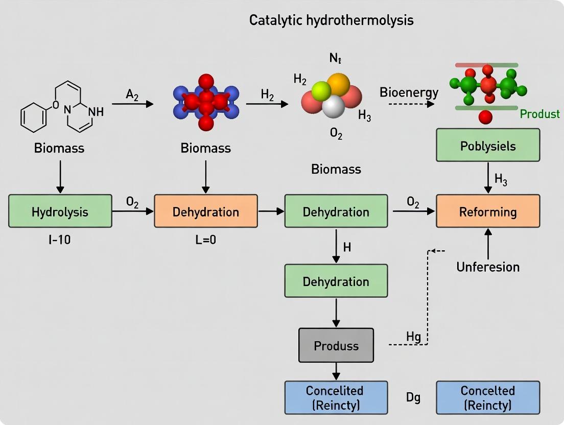
CHT Process Flow: Wet Biomass to Products
Lipid Conversion Pathway in CHT
The Scientist's Toolkit: Essential Research Reagents & Materials
| Item | Function in CHT Research |
|---|---|
| Subcritical Water Reactor | A high-pressure, corrosion-resistant (e.g., Hastelloy) batch or continuous system capable of maintaining temperatures up to 350°C and pressures up to 20 MPa. |
| Heterogeneous Catalysts | Solid acids (Zeolites, ZrO2), bases (Na2CO3, K2CO3), or metal catalysts (Pt, NiMo, Ru) supported on Al2O3/C to direct reaction pathways and improve oil quality. |
| Wet Biomass Feedstock | Standardized algae slurry (e.g., Nannochloropsis), lignocellulosic paste, or digested sewage sludge with characterized moisture and ash content. |
| Inert Pressurization Gas | High-purity N₂ or He to establish an inert atmosphere and provide initial system pressure, suppressing oxidative reactions. |
| Solvents for Product Recovery | Dichloromethane (DCM) or ethyl acetate for efficient liquid-liquid extraction of organic bio-oil from the aqueous phase post-reaction. |
| Elemental (CHNS) Analyzer | To determine the carbon, hydrogen, nitrogen, and sulfur content of the produced bio-oil, enabling O/C and H/C ratio calculations. |
| Bomb Calorimeter | To experimentally determine the Higher Heating Value (HHV) of the bio-oil, a key metric for fuel quality assessment. |
Introduction & Thesis Context Within the research domain of catalytic hydrothermolysis for wet biomass conversion, understanding the solvent and reaction medium is paramount. This thesis posits that the deliberate manipulation of subcritical water's properties serves as a foundational variable for optimizing depolymerization, hydrolysis, and downstream product recovery. Subcritical water (SCW), defined as liquid water under elevated temperature (100–374 °C) and sufficient pressure to maintain the liquid state (typically >0.1 MPa and <22.1 MPa), exhibits profoundly altered physiochemical properties. These changes enable it to replace traditional organic solvents for extraction and reaction, directly impacting the efficiency and selectivity of biomass conversion processes. This document provides application notes and protocols for leveraging SCW in a research setting.
1. Key Properties of Subcritical Water: Quantitative Data The properties of water change dramatically with increasing temperature under pressure. These changes are central to its utility in hydrothermal processing.
Table 1: Thermodynamic and Physicochemical Properties of Water Under Subcritical Conditions
| Property | Condition 1: 25°C, 0.1 MPa | Condition 2: 150°C, 0.5 MPa | Condition 3: 250°C, 4 MPa | Condition 4: 350°C, 17 MPa |
|---|---|---|---|---|
| Dielectric Constant (ε) | ~78.5 | ~50 | ~27 | ~14 |
| Ionic Product (pKw) | 14.0 | ~11.6 | ~11.2 | ~12.0 |
| Viscosity (mPa·s) | 0.89 | 0.19 | 0.11 | 0.07 |
| Density (g/cm³) | 0.997 | 0.92 | 0.80 | 0.57 |
| Diffusion Coefficient | Low | Increased | High | Very High |
2. Application Notes for Biomass Conversion
- Solvent Power Tuning: The dielectric constant drop (Table 1) shifts SCW from a polar solvent to one capable of dissolving organic compounds like lignin fragments and fatty acids, facilitating extraction and reaction homogeneity.
- Enhanced Reaction Rates: Reduced viscosity and increased diffusivity improve mass transfer into heterogeneous biomass matrices. The elevated temperature inherently increases reaction kinetics.
- Acid/Base Catalyst Replacement: The increased ionic product ([H⁺] and [OH⁻] concentrations peak near 250°C) means SCW can act as a self-neutralizing acid/base catalyst, promoting hydrolysis (e.g., of cellulose to sugars) without added mineral acids.
- Integration with Catalytic Hydrothermolysis: The solvent properties of SCW improve contact between solid biomass, water, and heterogeneous catalysts (e.g., Ru/C, ZrO₂), enhancing hydrodeoxygenation and other key catalytic steps.
3. Experimental Protocols
Protocol 3.1: Subcritical Water Extraction of Bioactive Compounds from Wet Biomass Objective: To extract lipophilic compounds from wet algal biomass using SCW. Materials: See Scientist's Toolkit. Method:
- Homogenize 10 g of wet algae paste (80% moisture) with 5 g of diatomaceous earth.
- Load mixture into the extraction cell of a pressurized fluid extractor (PFE) or a custom high-pressure reactor.
- Set reactor temperature to 180°C and pressure to 2.0 MPa. Use pre-heated water as solvent.
- Set static extraction time for 20 minutes, followed by a dynamic flush with fresh SCW (2 cell volumes).
- Collect effluent in a cooled vessel. Extract non-polar compounds from the aqueous effluent using ethyl acetate (3 x 20 mL).
- Dry the organic phase over anhydrous Na₂SO₄, filter, and concentrate under reduced pressure for analysis (GC-MS, HPLC).
Protocol 3.2: Hydrolysis of Cellulose in Subcritical Water for Sugar Platform Objective: To quantify the production of reducing sugars from microcrystalline cellulose. Materials: See Scientist's Toolkit. Method:
- Prepare a 2% (w/v) suspension of microcrystalline cellulose in deionized water.
- Load 10 mL of the suspension into a batch-type high-pressure reactor (e.g., Parr bomb).
- Purge the system with N₂, then pressurize to 5 MPa with N₂ at room temperature to ensure a liquid state upon heating.
- Rapidly heat the reactor to the target temperature (e.g., 240°C). Maintain with stirring for a precise reaction time (1-15 minutes).
- Quench the reaction by immersing the reactor in an ice-water bath.
- Upon reaching room temperature, carefully release pressure, collect contents, and filter (0.22 µm).
- Analyze filtrate for total reducing sugars (DNS assay), specific monomers (HPLC-RI), and potential degradation products (5-HMF, furfural) via HPLC-UV.
Protocol 3.3: In-situ pH Measurement in Subcritical Water Systems Objective: To estimate the in-situ ionic character of SCW during reaction. Method:
- Calibration: Prepare a series of neutral phosphate buffers. Subject them to identical SCW conditions (e.g., 200°C, 1.5 MPa) in sealed quartz capillaries for short durations.
- Analysis: Post-quenching, measure the room-temperature pH of the buffers. Plot the known room-temperature pKw-corrected pH against the measured pH to create a calibration curve for the system.
- Sample Measurement: Run an experimental SCW reaction with biomass. Quench and measure room-temperature pH immediately.
- Calculation: Use the calibration curve and the known temperature dependence of the dissociation constants for any added buffering species to back-calculate the approximate in-situ pH under reaction conditions.
4. Diagrams
SCW's Role in Biomass Valorization Pathway
General SCW Experimental Workflow
5. The Scientist's Toolkit: Key Research Reagent Solutions & Materials
Table 2: Essential Materials for Subcritical Water Experiments
| Item | Function / Explanation |
|---|---|
| Batch High-Pressure Reactor | Parr-type bomb or equivalent, with stirrer, pressure gauge, safety rupture disc, and corrosion-resistant alloy (Hastelloy, Inconel) for high-temperature aqueous use. |
| Pressurized Fluid Extractor (PFE) | Commercial system (e.g., ASE) for automated, safe, and reproducible SCW extractions at set T/P profiles. |
| Back-Pressure Regulator | Critical for maintaining liquid state by applying constant pressure above the vapor pressure at the operating temperature. |
| Quartz or Hastelloy Reaction Cells | Inert liners for batch reactors to prevent metal leaching and catalytic interference during experiments. |
| In-situ pH Sensors | Specialized potentiometric sensors with robust electrodes (e.g., ZrO₂-based) capable of withstanding SCW conditions for direct measurement. |
| Deionized & Degassed Water | Solvent. Degassing prevents unwanted oxidation and bubble formation during heating. |
| Cold Trap / Heat Exchanger | For rapidly quenching effluent from a continuous flow system or condensing vapors from a batch release. |
| Biomass Model Compounds | Cellulose, xylan, lignin (e.g., Organosolv), and triglycerides for controlled, interpretable reactivity studies. |
| Analytical Standards | 5-HMF, furfural, levulinic acid, sugar monomers (glucose, xylose), and phenolic monomers for product quantification via HPLC/GC. |
Within the broader thesis on catalytic hydrothermolysis (CHT) for wet biomass conversion, understanding and controlling the fundamental reaction pathways is paramount. CHT employs subcritical water (200-350°C, 5-20 MPa) and often catalysts to convert lipids, proteins, and carbohydrates in biomass into biofuels and biochemicals. The process is governed by four interlinked key pathways: Hydrolysis initiates depolymerization; Decarboxylation and Dehydration remove oxygen; and Repolymerization forms undesired solids. Balancing these pathways through catalyst and process design is the core challenge for optimizing yield and product quality.
Reaction Pathways: Mechanisms and Implications
Hydrolysis: The nucleophilic attack by water under high-temperature pressure, cleaving ester, amide, and glycosidic bonds. It is the primary depolymerization step for triglycerides (to fatty acids and glycerol), proteins (to peptides/amino acids), and carbohydrates (to sugars). Decarboxylation: Removal of a carboxyl group as CO₂ from fatty acids or amino acids. A critical oxygen-rejection route, increasing the heating value of organic products. Dehydration: Elimination of water molecules from alcohols, sugars, or polyols (e.g., glycerol to acrolein). It also contributes to oxygen removal and creates reactive intermediates. Repolymerization: Secondary condensation reactions (e.g., Maillard reactions between sugars and amino acids, aldol condensations) leading to the formation of insoluble, nitrogenous polymers often termed "humins" or "coke." This pathway is a major cause of carbon loss and reactor fouling.
Table 1: Typical Product Yields from Model Compounds in CHT (Catalyst: 5 wt% Na₂CO₃, 300°C, 30 min)
| Model Compound (Pathway Studied) | Hydrolysis Yield (%) | Decarboxylation Yield (CO₂%) | Dehydration Product Yield (%) | Repolymerization (Solid %) | Key Liquid Product & Yield |
|---|---|---|---|---|---|
| Soybean Oil (Hydrolysis/Decarb.) | >95 (to FFAs*) | 15-25 (from FFAs) | <5 | 2-8 | C15-C18 Alkanes/Alkenes (~60%) |
| Glucose (Dehydration/Repolym.) | N/A | N/A | 20-40 (to HMF/LA*) | 30-50 | Levulinic Acid (LA, up to 25%) |
| Alanine (Decarboxylation) | N/A | ~40 (CO₂) | <10 | 10-20 | Ethylamine (~35%) |
| Cellulose (Hydrolysis/Repolym.) | 70-90 (to sugars) | N/A | 15-30 (from sugars) | 20-40 | Total Organic Carbon in Liquid (~50%) |
*FFAs: Free Fatty Acids. HMF: 5-Hydroxymethylfurfural. *LA: Levulinic Acid.
Table 2: Effect of Catalyst on Pathway Selectivity (350°C, 1 hr)
| Catalyst Type (1 M) | Hydrolysis Rate Constant (k_h, min⁻¹) | Decarboxylation Selectivity (%) | Repolymerization Reduction vs. No Cat. (%) | Primary Role |
|---|---|---|---|---|
| None (Water only) | 0.05 | 10 | 0 (Baseline) | Promotes hydrolysis & repolymerization |
| Na₂CO₃ (Base) | 0.12 | 35 | 25 | Enhances hydrolysis & decarboxylation |
| H₃PO₄ (Acid) | 0.15 | 5 | -20 (Increases) | Drives hydrolysis & dehydration |
| Ni/SiO₂-Al₂O₃ (Metal/Acid) | 0.08 | 55 | 60 | Strong decarboxylation/hydrogenation, inhibits repolym. |
Experimental Protocols
Protocol 1: Assessing Hydrolysis and Decarboxylation Pathways Using Lipid Feedstock Objective: Quantify the extent of hydrolysis and decarboxylation during CHT of triglycerides. Materials: Batch reactor (e.g., 100 mL Parr), canola oil, sodium carbonate, water, gas bag, GC-MS, TAN titration kit. Procedure: 1. Charge reactor with 10 g oil, 40 g deionized water, and 0.5 g Na₂CO₃. 2. Purge with N₂, pressurize to 5 MPa with inert gas, heat to 300°C with stirring (600 rpm) for 60 min. 3. Cool rapidly in an ice bath. Collect gas product in a sealed bag via a reactor vent. 4. Measure gas volume and analyze CO₂ content by GC-TCD. 5. Separate aqueous/organic liquid phases. Titrate organic phase to determine Total Acid Number (TAN), calculating free fatty acid yield (hydrolysis extent). 6. Analyze organic phase via GC-MS for hydrocarbon products (decarboxylation/dehydration products).
Protocol 2: Monitoring Repolymerization via Solid Residue Analysis Objective: Measure solid ("humins") formation from carbohydrate feeds. Materials: Batch reactor, glucose, alanine, phosphate buffer (pH 7), vacuum oven, 0.2 μm PTFE filter. Procedure: 1. Charge reactor with 5 g glucose, 1 g alanine, 50 mL 0.1M phosphate buffer. 2. Conduct reaction at 250°C for 30 min. 3. Cool, dilute reaction slurry with 100 mL warm DI water. 4. Filter through pre-weighed 0.2 μm PTFE membrane. 5. Wash solid residue thoroughly with water and methanol. 6. Dry filter+solids in a vacuum oven at 80°C overnight. 7. Weigh filter to determine mass of insoluble solid residue (repolymerization product). 8. Analyze solids via FTIR or elemental analysis (C, H, N, O).
Visualization of Pathways and Workflow
Title: Interplay of Key Reaction Pathways in Hydrothermolysis
Title: General CHT Batch Experiment Workflow
The Scientist's Toolkit: Key Research Reagent Solutions & Materials
Table 3: Essential Materials for CHT Pathway Studies
| Item | Function/Application | Notes |
|---|---|---|
| Subcritical Water | Primary solvent and reactant for hydrolysis. | Deionized, degassed. Temperature controls reaction network. |
| Na₂CO₃ (Sodium Carbonate) | Homogeneous base catalyst. Promotes hydrolysis of esters/amides and decarboxylation. | Common for lipid conversion. Concentration tunes pH. |
| H₃PO₄ (Phosphoric Acid) | Homogeneous acid catalyst. Drives hydrolysis and dehydration (e.g., of sugars). | Can accelerate repolymerization; requires careful control. |
| Ni/SiO₂-Al₂O₃ Catalyst | Bifunctional heterogeneous catalyst. Metal site promotes decarb./hydrog., acid site aids hydrolysis. | Effective for direct hydrodeoxygenation, reduces solids. |
| Model Compounds (e.g., Soybean Oil, Glucose, Alanine, Cellulose) | Simplifies study of specific pathways from complex biomass. | Allows for precise mechanistic and kinetic studies. |
| High-Pressure Batch Reactor (Parr, Berghof) | Contains high-temperature, high-pressure aqueous reactions. | Must be corrosion-resistant (Hastelloy), with stirring and temp control. |
| 0.2 μm PTFE Filter Membrane | Quantitative separation of solid repolymerization products (humins). | Chemically inert, withstands washing solvents. |
| GC-TCD/FID & GC-MS Systems | Quantifies gas (CO₂, CH₄) and volatile liquid products (alkanes, acids, furans). | Essential for decarboxylation and dehydration product analysis. |
| Total Acid Number (TAN) Titration Kit | Measures free fatty acid concentration, quantifying hydrolysis extent of lipids. | Simple, rapid analytical method. |
Within catalytic hydrothermolysis (CHT) for wet biomass conversion, catalysts are pivotal in deconstructing complex biopolymers (lignin, cellulose, hemicellulose) and facilitating deoxygenation reactions under sub- or supercritical water conditions. The choice between homogeneous and heterogeneous catalysis fundamentally dictates process design, separation efficiency, and product profiles.
- Homogeneous Catalysts (e.g., K₂CO₃, H₂SO₄, NaOH): These catalysts operate in the same aqueous phase as the biomass slurry. They offer high accessibility and uniform active sites, leading to high initial reaction rates and effectiveness in solubilizing biomass. However, they necessitate costly neutralization and separation steps post-reaction, leading to salt waste streams and potential catalyst recovery challenges.
- Heterogeneous Catalysts (e.g., Pt/γ-Al₂O₃, ZrO₂, Ru/C): These solid catalysts are physically distinct from the reaction medium. They enable facile separation (e.g., filtration), reusability, and often greater selectivity towards desired fuel intermediates. Challenges include potential deactivation via coking, sintering, or leaching under harsh hydrothermal conditions, and mass transfer limitations.
Key Application Insights:
- Alkali Catalysts (Homogeneous): Excellent for hydrolyzing and solubilizing lignin, enhancing bio-crude yield from algae and lignocellulosics, but can promote soap formation.
- Acid Catalysts: Mineral acids (homogeneous) are potent for sugar dehydration but are highly corrosive. Solid acids like sulfated zirconia (heterogeneous) offer a recyclable alternative for esterification and hydrolysis.
- Metal Oxides (Heterogeneous): Redox-active oxides (e.g., CeO₂, TiO₂) facilitate selective deoxygenation via decarboxylation/decarbonylation. Supported noble metals (Pt, Ru) on stable carriers are premier catalysts for hydrodeoxygenation (HDO) within CHT processes.
Table 1: Performance Comparison of Catalyst Types in Model CHT Reactions (Microalgae Nannochloropsis sp., 350°C, 60 min)
| Catalyst | Type | Loading (wt.%) | Bio-crude Yield (wt.%) | HHV (MJ/kg) | Deoxygenation (wt.% O) | Key Advantage | Key Disadvantage |
|---|---|---|---|---|---|---|---|
| None (Thermal) | N/A | 0 | 35.2 | 34.5 | 12.1 | No catalyst cost | High O-content, low yield |
| K₂CO₃ | Homogeneous | 5 | 45.8 | 36.1 | 10.5 | High yield boost | Salt waste, difficult recovery |
| H₂SO₄ | Homogeneous | 1 | 38.5 | 37.8 | 8.9 | Effective deoxygenation | Severe corrosion, neutralization |
| 5% Pt/γ-Al₂O₃ | Heterogeneous | 10 | 42.3 | 39.5 | 6.2 | Excellent deoxygenation, separable | Cost, possible metal leaching |
| ZrO₂ | Heterogeneous | 20 | 39.1 | 37.2 | 9.8 | Stable, no leaching | Moderate activity |
Table 2: Catalyst Stability & Reusability in Continuous CHT (Wood Slurry, 300°C, 20 MPa)
| Catalyst | Cycle | Bio-crude Yield (wt.%) | BET SA Loss (%) | Metal Leaching (ppm) | Coke Deposition (wt.%) |
|---|---|---|---|---|---|
| 5% Ru/C | 1 | 41.5 | 0 | <0.5 | 2.1 |
| 3 | 40.8 | 12 | 1.2 | 5.8 | |
| 5 | 38.2 | 28 | 3.5 | 11.4 | |
| HZSM-5 | 1 | 33.7 | 0 | N/A | 4.3 |
| 3 | 30.1 | 35 | N/A | 15.2 |
Experimental Protocols
Protocol 1: CHT with Homogeneous Alkali Catalyst (K₂CO₃) for Algal Biomass
Objective: To convert wet microalgae to bio-crude with enhanced yield using a homogeneous catalyst. Materials: See Scientist's Toolkit. Procedure:
- Slurry Preparation: Blend 100 g of wet algae paste (80% moisture) with 400 ml deionized water. Add 5.0 g K₂CO₃ (5 wt.% of dry algae mass). Homogenize for 10 min.
- Reactor Loading: Charge 50 g of the slurry into a 100 ml high-pressure batch reactor (e.g., Parr autoclave).
- Reaction: Purge the reactor headspace with N₂ (3 cycles, 10 bar). Pressurize to 20 bar N₂. Heat to 350°C at a rate of ~10°C/min, with constant stirring (600 rpm). Hold at 350°C for 60 minutes.
- Quenching & Collection: Cool the reactor rapidly in an ice-water bath. Collect gas in a sampling bag. Transfer the liquid-solid mixture to a centrifuge tube.
- Product Separation: Centrifuge at 8000 rpm for 15 min. Separate the top aqueous layer. Wash the solid residue (bio-char + catalyst salts) with dichloromethane (DCM). Combine the DCM wash with the insoluble bottom organic (bio-crude) layer.
- Recovery: Remove DCM via rotary evaporation (40°C, 200 mbar) to obtain the raw bio-crude. Weigh and analyze (GC-MS, CHNS/O).
Protocol 2: CHT with Heterogeneous Catalyst (Pt/γ-Al₂O₃) & Catalyst Reusability Test
Objective: To convert lignocellulosic slurry to deoxygenated bio-crude and assess catalyst stability. Materials: See Scientist's Toolkit. Procedure:
- Catalyst Pre-treatment: Reduce 2.0 g of 5% Pt/γ-Al₂O₃ catalyst in a quartz tube under H₂ flow (50 ml/min) at 400°C for 2 hours. Cool under N₂.
- Slurry & Loading: Prepare a 10 wt.% slurry of pine wood powder in water. Load 40 g of slurry and 2.0 g of pre-reduced catalyst into the batch reactor.
- Reaction: Seal, purge with H₂ (5 bar, 3 cycles). Pressurize with H₂ to 30 bar at room temperature. Heat to 330°C (10°C/min) and hold for 90 min with stirring.
- Product Separation: Cool, vent gas for analysis. Filter the mixture through a 0.45 µm PTFE membrane to recover the solid catalyst. Extract the filtrate with DCM in a separatory funnel to isolate bio-crude.
- Catalyst Regeneration & Reuse: Wash the recovered catalyst with acetone, then dry at 105°C for 12h. Calcine in static air at 500°C for 4h to remove coke. Repeat reduction (Step 1) and reaction (Steps 2-4) for stability testing.
- Analysis: Characterize spent/regenerated catalyst via TPO (for coke), ICP-OES (for leaching), and N₂ physisorption.
Visualizations
Diagram Title: Homogeneous vs Heterogeneous CHT Process Flow
Diagram Title: Key Catalytic Pathways in CHT Biomass Conversion
The Scientist's Toolkit: Research Reagent Solutions
| Item | Function in CHT Experiments |
|---|---|
| High-Pressure Batch Reactor (e.g., Parr, Berghof) | Provides controlled, high-temperature, high-pressure environment for hydrothermal reactions. Must be corrosion-resistant (Hastelloy). |
| Wet Biomass Feedstocks (Microalgae paste, lignocellulosic slurry) | Primary substrate. Consistency in moisture & particle size is critical for reproducibility. |
| Homogeneous Catalysts (K₂CO₃, H₂SO₄, NaOH) | Highly active, soluble catalysts for hydrolysis and depolymerization. Require post-processing. |
| Heterogeneous Catalysts (5% Pt/γ-Al₂O₃, Ru/C, ZrO₂) | Solid, separable catalysts for HDO and reforming. Enable reuse studies. |
| Dichloromethane (DCM) | Solvent for extracting organic bio-crude from the aqueous post-reaction mixture. |
| Rotary Evaporator | For gentle removal of extraction solvents (like DCM) from the bio-crude product. |
| GC-MS / GC-FID System | For identifying and quantifying volatile organic compounds in bio-crude and aqueous phases. |
| CHNS/O Elemental Analyzer | For determining the carbon, hydrogen, nitrogen, sulfur, and oxygen content of solid and liquid products. |
| ICP-OES | To analyze catalyst metal leaching into the aqueous phase, critical for stability assessment. |
| Surface Area & Porosity Analyzer (BET) | To measure catalyst surface area and pore volume changes after reaction (deactivation). |
Application Notes
Feedstock flexibility in catalytic hydrothermolysis (CHT) represents a critical technological advancement for the valorization of diverse high-moisture biomass streams. Within a broader thesis on CHT for wet biomass conversion, this flexibility directly addresses economic and logistical bottlenecks by enabling the use of low-cost, widely available, and often problematic waste streams without energy-intensive drying. The inherent advantages of processing algae, sewage sludge, and food waste are quantified in Table 1.
Table 1: Comparative Analysis of High-Moisture Biomass Feedstocks for Catalytic Hydrothermolysis
| Feedstock Parameter | Microalgae (e.g., Chlorella) | Sewage Sludge | Food Waste (Pre-processed) |
|---|---|---|---|
| Typical Moisture Content (%) | 80-95 | 95-98 | 70-85 |
| Key Advantage for CHT | High growth rate, CO₂ sequestration, does not compete with arable land. | Waste remediation, reduction of landfill/incineration volumes, constant supply. | High organic/volatile solids content, high biodegradability, high energy potential. |
| Primary CHT Product Focus | Bio-crude oil, nutraceuticals, hydrochar. | Bio-crude oil, nutrient recovery (P, N), solid fuel (hydrochar). | Bio-crude oil, platform chemicals (e.g., levulinic acid, HMF), biogas precursors. |
| Typical Catalyst Systems | Homogeneous (e.g., K₂CO₃, Na₂CO₃), Heterogeneous (e.g., ZrO₂, Pt/C). | Heterogeneous (e.g., Ru/C, MoS₂), waste-derived catalysts (e.g., red mud). | Homogeneous (e.g., CH₃COOH, HCl), Heterogeneous (e.g., zeolites, carbon supports). |
| Key Challenge for CHT | High protein content leads to N/O heteroatoms in bio-oil, requiring downstream upgrading. | Ash/inorganic content, potential toxic elements (e.g., heavy metals), pathogens. | Feedstock heterogeneity, seasonal variability, high acidity of products. |
| Reported Bio-crude Yield Range (wt.%, dry ash-free) | 25-50% | 30-45% | 35-60% |
| Higher Heating Value (HHV) of Bio-crude (MJ/kg) | 30-38 | 35-40 | 32-37 |
The principal advantage lies in the synergy between the aqueous processing environment of CHT (typically at 250-374°C and 4-22 MPa) and the natural state of these feedstocks. Subcritical water acts as a solvent, reactant, and catalyst, facilitating hydrolysis, decarboxylation, and repolymerization reactions. The flexibility to process multiple feedstocks with minimal pretreatment allows for the establishment of decentralized, regional biorefineries tailored to local waste streams.
Experimental Protocols
Protocol: Standardized CHT Reactor Operation for Feedstock Comparison
This protocol outlines a standardized procedure for comparing the conversion efficiency of different high-moisture biomass feedstocks (algae paste, dewatered sewage sludge, and food waste slurry) under identical catalytic hydrothermolysis conditions.
Aim: To quantitatively assess bio-crude yield and quality from diverse wet feedstocks using a batch CHT system.
Materials & Equipment:
- High-Pressure Batch Reactor: Parr instrument or equivalent, 500 mL capacity, equipped with stirrer, heating mantle, temperature/pressure controllers, and safety rupture disc.
- Feedstock Preparation: Blender, vacuum filtration setup, moisture analyzer.
- Post-Reaction Separation: Dichloromethane (DCM), separation funnel, centrifuge, rotary evaporator, oven.
- Catalyst: Sodium carbonate (Na₂CO₃) solution (1M) as a homogeneous base catalyst.
- Analytical: Elemental analyzer (CHNS/O), bomb calorimeter, GC-MS.
Procedure:
- Feedstock Standardization: Homogenize each feedstock (algae, sludge, food waste) separately. Adjust the solid content to 15% total solids (TS) using deionized water. Record exact TS for mass balance.
- Reactor Loading: Charge 200 g of the standardized feedstock slurry into the reactor. Add 20 mL of 1M Na₂CO₃ catalyst solution. Seal the reactor.
- Reaction Phase: Purge the reactor headspace with N₂ (3 cycles, 10 bar). Set stirring to 500 rpm. Heat to the target temperature of 300°C at a ramp rate of ~10°C/min. Maintain reaction temperature at 300°C for 30 minutes. Monitor and record pressure (expected 8-12 MPa).
- Quenching & Depressurization: After the hold time, cool the reactor rapidly using an internal cooling coil or cold-water bath to below 50°C. Slowly vent gaseous products through a gas sampling bag or vent.
- Product Recovery: Open the reactor. Transfer the entire product mixture to a separation funnel. Add 100 mL DCM to extract bio-crude. Shake vigorously for 10 minutes and allow phases to separate. Collect the organic (DCM + bio-crude) layer.
- Separation & Drying: Repeat the DCM extraction twice on the aqueous/solid residue. Combine all DCM extracts. Dry the combined organic phase over anhydrous Na₂SO₄. Filter and remove DCM using a rotary evaporator (40°C). Weigh the recovered bio-crude.
- Analysis: Calculate bio-crude yield on a dry ash-free (daf) feedstock basis. Characterize using elemental analysis and GC-MS.
Protocol: Sequential Hydrothermal Liquefaction & Aqueous Phase Reforming for Maximum Carbon Recovery
This protocol details a two-step process to maximize carbon conversion from high-moisture biomass, first to bio-crude (HTL) and then catalytically reforming the organic-rich aqueous phase.
Aim: To minimize carbon loss in the aqueous phase by converting water-soluble organics into additional valuable gases (H₂, CH₄) or platform chemicals.
Materials & Equipment:
- Two-Reactor System: Primary CHT reactor (as in 2.1) and a secondary fixed-bed or batch reactor for aqueous phase reforming (APR).
- APR Catalyst: 5% Pt/Al₂O₃ pellets (reduced).
- Gas Collection: Gas bags, GC with TCD for syngas analysis.
Procedure:
- Step 1 - Primary CHT: Perform CHT as per Protocol 2.1 using algae paste as feedstock. Recover the bio-crude via DCM extraction as described. Retain the separated aqueous phase.
- Aqueous Phase Characterization: Filter the aqueous phase (0.45 µm). Analyze for Total Organic Carbon (TOC) and pH.
- Step 2 - Aqueous Phase Reforming: Load the APR reactor with 5g of 5% Pt/Al₂O₃ catalyst. Pre-reduce catalyst under H₂ flow at 350°C for 2 hours. Pump the filtered aqueous phase into the APR reactor at 225°C and 2.8 MPa under N₂ atmosphere. Maintain a liquid hourly space velocity (LHSV) of 2 h⁻¹.
- Product Collection: Collect effluent liquid and gas products separately over a 1-hour period. Analyze the gas composition via GC-TCD.
Visualizations
CHT and APR Integrated Experimental Workflow
Simplified Reaction Pathways in Biomass CHT
The Scientist's Toolkit: Research Reagent Solutions
Table 2: Essential Materials for Catalytic Hydrothermolysis Research
| Item/Chemical | Function in CHT Experiments | Key Considerations |
|---|---|---|
| High-Pressure Batch Reactor (e.g., Parr) | Provides contained environment for reactions at subcritical water conditions (T > 200°C, P > 2 MPa). | Material must be corrosion-resistant (Hastelloy, Inconel). Safety features (rupture disc, pressure relief) are mandatory. |
| Homogeneous Catalyst: K₂CO₃ / Na₂CO₃ | Base catalyst promoting hydrolysis, deoxygenation, and stabilizing intermediates. Increases bio-crude yield. | Effective for high-protein feedstocks (algae). Requires recovery/recycling from aqueous phase. |
| Heterogeneous Catalyst: 5% Pt/Al₂O₃ | Used for downstream aqueous phase reforming (APR) to produce H₂ from water-soluble organics. | High cost necessitates stability studies. Sensitive to sulfur/chloride poisoning. |
| Dichloromethane (DCM) | Standard solvent for quantitatively extracting bio-crude from the aqueous/solid product mixture post-reaction. | High volatility and toxicity require use in fume hood. Alternatives like ethyl acetate can be explored. |
| Anhydrous Sodium Sulfate (Na₂SO₄) | Drying agent used to remove trace water from the DCM-bio-crude extract prior to solvent evaporation. | Must be freshly baked to ensure anhydrous state. Remove by filtration. |
| Total Organic Carbon (TOC) Analyzer | Critical for quantifying carbon distribution, especially the organic carbon remaining in the aqueous phase post-CHT. | Measures process efficiency and carbon closure for mass balance. |
| Elemental Analyzer (CHNS/O) | Determines the elemental composition (C, H, N, S) of raw biomass and produced bio-crude. Essential for calculating HHV and heteroatom content. | Requires small, homogeneous samples. Oxygen often calculated by difference. |
Application Notes: Product Streams from Catalytic Hydrothermolysis (CHT)
Within the context of advancing Catalytic Hydrothermolysis for Wet Biomass Conversion, the primary output streams—Biocrude, Aqueous Phase Organics (APO), and Gas Phase Products—represent both targeted fuels and valuable chemical feedstocks. The distribution and composition of these products are critical for assessing process efficiency and economic viability.
Bio-crude (Biocrude): This is the primary energy-dense target, a complex emulsion of hydrocarbons, fatty acids, alcohols, ketones, and nitrogenous compounds. Its quality, particularly its oxygen, nitrogen, and sulfur content, directly dictates the required downstream hydrotreating severity for renewable diesel or jet fuel production.
Aqueous Phase Organics (APO): This stream contains water-soluble organics (e.g., acetic acid, formic acid, glycols, sugars) and inorganic salts leached from the biomass. It represents a significant carbon loss if not valorized but is a potential source for biochemical production or a nutrient source for fermentation.
Gas Phase Products: Primarily consists of CO₂ (from decarboxylation), CO, H₂, CH₄, and lighter hydrocarbons (C1-C4). The composition provides insight into the dominant reaction pathways (e.g., decarboxylation vs. decarbonylation) and the mass balance of the process.
Table 1: Typical Product Yields and Characteristics from CHT of Model Feedstocks
| Feedstock | Catalyst | Conditions (T, P, Time) | Biocrude Yield (wt%) | APO C-Content (g/L) | Major Gas Components | Reference |
|---|---|---|---|---|---|---|
| Microalgae (Nannochloropsis) | 5% Na₂CO₃ | 350°C, 20 MPa, 60 min | 45.2 | 12.5 (TOC) | CO₂ (~85%), CH₄ (~8%) | (Valdez et al., 2014) |
| Sewage Sludge | FeSO₄ | 300°C, 10 MPa, 30 min | 38.7 | 8.2 (TOC) | CO₂ (~75%), H₂ (~15%) | (Zhang et al., 2020) |
| Food Waste | Ru/C | 400°C, 25 MPa, 15 min | 55.1 | 20.1 (COD) | CO₂ (~60%), CH₄ (~25%) | (Yang et al., 2022) |
| Lignocellulosic Slurry (Pine) | Ni/TiO₂ | 330°C, 18 MPa, 45 min | 32.5 | 15.8 (TOC) | CO₂ (~70%), CO (~20%) | (Kumar & Gupta, 2023) |
Table 2: Key Analytical Methods for Product Characterization
| Product Stream | Key Analytical Technique | Target Parameters/Compounds |
|---|---|---|
| Biocrude | Elemental Analysis (CHNS/O) | C, H, N, S, O content; HHV calculation |
| GC-MS / FT-ICR MS | Molecular speciation, compound classes | |
| Simulated Distillation (SimDis) | Boiling point distribution | |
| Aqueous Phase | TOC/COD Analyzer | Total organic carbon, chemical oxygen demand |
| HPLC/IC | Carboxylic acids, sugars, alcohols, inorganic ions | |
| GC-MS (after derivatization) | Volatile organic acids and neutrals | |
| Gas Phase | Micro-GC/TCD | Permanent gases (H₂, CO, CO₂, CH₄, C2-C4) |
Experimental Protocols
Protocol 2.1: Bench-Scale Catalytic Hydrothermolysis and Product Separation
Objective: To convert wet biomass into separable streams of biocrude, aqueous phase, and gas products, and to quantify yields.
Materials: See The Scientist's Toolkit below.
Methodology:
- Feedstock Preparation: Homogenize wet biomass (e.g., algae slurry, food waste) to a consistent particle size. Determine moisture content via oven drying (105°C until constant weight).
- Reactor Loading: Charge the high-pressure batch reactor (e.g., 100 mL Parr reactor) with a known mass of wet biomass (typically 20-30 g) and the specified catalyst (e.g., 5 wt% Na₂CO₃ relative to dry biomass). Seal the reactor.
- Inert Atmosphere: Purge the reactor headspace 3-5 times with inert gas (N₂ or Ar) at moderate pressure (10-15 bar) to displace oxygen.
- Reaction: Heat the reactor to the target temperature (e.g., 300-400°C) at a fixed heating rate (e.g., 10°C/min) under constant stirring (500-700 rpm). Maintain at setpoint for the specified reaction time (15-60 min). Record pressure.
- Quenching & Gas Collection: After the reaction, quench the reactor in an ice-water bath. Connect the gas outlet to a gas bag or a calibrated gas collection vessel via a pressure-regulated line. Slowly release and collect the gas phase. Measure final gas volume and pressure.
- Product Recovery: a. Open the reactor. Transfer the entire contents (a biphasic mixture) into a separatory funnel. b. Rinse the reactor interior with a minimal volume of dichloromethane (DCM) or ethyl acetate, adding rinsates to the separatory funnel. c. Allow phases to separate for 24 hours. The lower aqueous phase contains APO. The organic phase (biocrude + solvent) is the upper layer if DCM is used. d. Drain and collect the aqueous phase. Filter through a 0.45 µm filter. Analyze for TOC/COD and store at 4°C. e. Collect the organic phase in a pre-weighed flask.
- Biocrude Recovery: Remove the solvent from the organic phase using a rotary evaporator (40°C, reduced pressure). Dry the resulting biocrude under a gentle N₂ stream to constant weight. Record mass.
- Yield Calculation:
- Biocrude Yield (wt%) = (Mass of biocrude / Mass of dry biomass input) * 100
- Gas Yield (wt%) estimated via mass balance or detailed gas analysis.
- Solid Residue (wt%) = (Mass of dried solids post-reaction / Mass of dry biomass input) * 100
- APO Yield (wt%) is typically inferred by difference or quantified via TOC.
Protocol 2.2: Fractionation and Analysis of Aqueous Phase Organics (APO) via Solid-Phase Extraction (SPE)
Objective: To isolate and concentrate different organic compound classes from the APO for subsequent analysis or bioactivity testing.
Methodology:
- APO Pretreatment: Acidify the filtered APO sample to pH ~2 using 2M HCl. Centrifuge to remove any precipitated solids.
- SPE Column Conditioning: Condition a reverse-phase C18 SPE cartridge sequentially with 5 mL methanol, followed by 5 mL acidified water (pH 2 with HCl).
- Sample Loading: Load the acidified APO sample onto the cartridge at a slow, steady rate (~1-2 mL/min).
- Fraction Elution: a. Fraction 1 (Hydrophilic Neutrals/Acids): Elute with 5 mL of acidified water (pH 2). Contains most sugars and very short-chain acids. b. Fraction 2 (Organic Acids/Neutrals): Elute with 5 mL of diethyl ether. Contains acetic, propionic, butyric acids, and phenolics. c. Fraction 3 (Less Polar Organics): Elute with 5 mL of methanol. Contains longer-chain organics, alcohols, and less polar compounds.
- Concentration: Evaporate each eluted fraction to dryness under a gentle stream of N₂. Reconstitute in an appropriate solvent (e.g., water for Fraction 1, methanol for others) for HPLC, GC-MS, or biological assays.
Mandatory Visualization
Catalytic Hydrothermolysis Product Separation Workflow
APO Fractionation via Solid-Phase Extraction
The Scientist's Toolkit: Key Research Reagent Solutions & Materials
Table 3: Essential Materials for CHT Experiments
| Item/Category | Function/Application | Key Specifications/Notes |
|---|---|---|
| High-Pressure Batch Reactor | Contains the CHT reaction at sub/supercritical water conditions. | Must be corrosion-resistant (Hastelloy, Inconel); equipped with stirrer, heater, thermocouple, pressure gauge. |
| Heterogeneous Catalyst (e.g., Ni/TiO₂) | Enhances reaction rate, improves biocrude yield & quality. | Pre-sulfided forms may be used for hydrodeoxygenation. Loadings typically 1-10 wt% of dry biomass. |
| Homogeneous Catalyst (e.g., Na₂CO₃, K₂HPO₄) | Promotes hydrolysis, neutralizes acids, reduces char. | Water-soluble. Simplifies recovery but necessitates catalyst separation from APO. |
| Co-solvent (e.g., Ethanol, Isopropanol) | Improves biomass solubility and biocrude separation. | Can lower required reaction severity. Must be accounted for in mass balance. |
| Dichloromethane (DCM) | Primary solvent for biocrude recovery from the product slurry. | Effective for non-polar organics; low boiling point aids removal. Handle in fume hood. |
| Solid-Phase Extraction (SPE) Cartridges (C18) | Fractionates APO into compound classes for analysis or bio-testing. | Enables isolation of organic acids, phenolics, and neutrals from the complex aqueous matrix. |
| Internal Standards (for GC-MS) | Enables quantitative analysis of biocrude and APO components. | e.g., Deuterated n-alkanes for biocrude; 2-ethylbutyric acid for aqueous acids. |
| Calibration Gas Mixture (for Micro-GC) | Quantifies gas phase product composition. | Contains known concentrations of H₂, CO, CO₂, CH₄, C2-C4 in N₂ balance. |
How to Perform Catalytic Hydrothermolysis: Reactor Designs, Process Parameters, and Biomedical Applications
Within the thesis framework of Catalytic Hydrothermolysis (CHT) for Wet Biomass Conversion, selecting the appropriate reactor configuration is critical for bridging the gap between discovery and industrial application. CHT operates in hot, compressed water (e.g., 250-350°C, 5-20 MPa) with catalysts to deoxygenate and crack biomass into bio-crude. Each reactor type presents distinct advantages and challenges for this demanding process.
- Batch Reactors (Bench-Scale): Ideal for initial feasibility studies, parameter screening (T, P, catalyst loading), and feedstock variability assessment. High-pressure autoclaves allow for precise control but suffer from thermal gradients, long heat-up/cool-down times, and difficulty in catalyst recovery.
- Continuous-Flow Stirred-Tank Reactors (CSTRs) (Pilot-Scale): Provide uniform temperature and composition due to vigorous mixing, enabling accurate kinetic studies and steady-state operation. Essential for testing catalyst slurries or homogeneous catalysts in CHT. Challenges include potential for back-mixing and complex sealing for high-pressure slurry handling.
- Tubular (Plug Flow) Reactors (PFRs) (Bench & Pilot-Scale): Mimic ideal plug flow, offering a clear progression of reaction time and minimizing back-mixing. Highly suited for scaling CHT processes, as they allow for precise control of residence time and facilitate continuous catalyst packing (fixed-bed) or slurry flow. Key issues are potential plugging from solids and maintaining isothermal conditions over long lengths.
Table 1: Comparative Analysis of Reactor Configurations for Catalytic Hydrothermolysis
| Parameter | Batch Reactor | Continuous Stirred-Tank Reactor (CSTR) | Tubular/Plug Flow Reactor (PFR) |
|---|---|---|---|
| Primary Scale | Bench (0.1 - 2 L) | Pilot (1 - 20 L) | Bench & Pilot (0.1 - 10 L) |
| Operation Mode | Discontinuous | Continuous | Continuous |
| Residence Time Control | Fixed per batch | Controlled by flow rate & volume | Controlled by flow rate & length |
| Mixing | Variable (stirred) | Excellent (well-mixed) | Laminar to turbulent flow |
| Temperature Gradient | Can be significant | Minimal (well-mixed) | Axial gradient possible |
| Ideal For (CHT Context) | Catalyst screening, feedstock testing | Kinetic studies, slurry catalysis | Scalable process, fixed-bed catalysis |
| Key Challenge (CHT) | Slow cycles, thermal lag | Slurry handling & sealing | Solids plugging, wall effects |
| Typical Biomass Throughput | 50 - 500 g/batch | 1 - 10 kg/hr | 0.5 - 5 kg/hr |
Experimental Protocols
Protocol 2.1: Batch CHT of Microalgae in a High-Pressure Autoclave
Aim: To assess the bio-crude yield and quality from Nannochloropsis sp. using a heterogeneous catalyst (5% Ni/Al₂O₃).
Materials: See "The Scientist's Toolkit" below. Procedure:
- Load the 1-L autoclave with 150 g of wet algae paste (80% moisture), 1.5 g of catalyst, and 100 mL of deionized water.
- Seal the reactor, purge three times with N₂ (50 bar), then pressurize to 30 bar N₂ at room temperature.
- Heat the reactor to the target temperature (300°C) at a ramp rate of ~10°C/min under constant stirring (500 rpm).
- Maintain at 300°C for 60 minutes (reaction time).
- Cool the reactor rapidly using an internal cooling coil or external quenching bath to <50°C within 15 minutes.
- Slowly vent gaseous products through a condenser and gas sampling bag.
- Open the reactor. Recover the liquid product mixture and wash solids with dichloromethane (DCM).
- Separate the aqueous and organic (DCM) phases in a separatory funnel. The DCM phase contains bio-crude.
- Evaporate DCM using a rotary evaporator (40°C) to obtain the final bio-crude. Weigh and analyze via GC-MS/FID.
- Filter and dry the remaining solid residue to determine mass balance.
Protocol 2.2: Continuous-Flow CHT in a Tubular Fixed-Bed Pilot System
Aim: To demonstrate continuous conversion of sewage sludge slurry over a fixed-bed ruthenium-based catalyst.
Materials: See "The Scientist's Toolkit" below. Procedure:
- Slurry Preparation: Homogenize 1 kg of digested sewage sludge (20% total solids) with 4 L of deionized water. Mill to <200 µm particles.
- Reactor Packing: Load a tubular Hastelloy reactor (ID=2.5 cm, L=100 cm) with 500 mL of supported Ru/C catalyst pellets (1-2 mm). Fill void spaces with inert ceramic beads.
- System Pressurization: With the slurry feed paused, pressurize the entire system (feed line, reactor, back-pressure regulator) to 180 bar using high-pressure HPLC pumps delivering deionized water. Set the reactor furnace to 350°C.
- Feed Introduction & Steady-State: Once temperature and pressure are stable, switch the pump inlet from water to the biomass slurry. Set a constant flow rate of 2 L/hr, yielding a calculated residence time of ~15 minutes.
- Operation & Monitoring: Operate continuously for 8 hours. Monitor pressure drop across the reactor. Collect liquid effluent in a cooled, high-pressure separator every 30 minutes. Sample gas composition online via a micro-GC.
- Product Workup: Allow the collected liquid to phase separate. Measure aqueous phase volume and acidity (pH). Extract the organic bio-crude layer (if not fully separated, use DCM extraction). Quantify yields relative to dry ash-free biomass input.
- Shutdown: Switch pump feed back to water and flush the system for 30 minutes. Cool under pressure before depressurizing and unpacking the catalyst bed for analysis.
Visualization of Workflows & Relationships
Continuous Flow CHT Process Block Diagram
Reactor Configuration Selection Logic for CHT
The Scientist's Toolkit: Key Research Reagent Solutions & Materials
Table 2: Essential Materials for Catalytic Hydrothermolysis Reactor Experiments
| Item | Function in CHT Research | Example/Note |
|---|---|---|
| Wet Biomass Feedstock | Primary reactant. High moisture content is acceptable. | Microalgae paste, sewage sludge, food waste. Characterize for C/H/O/N, moisture, ash. |
| Heterogeneous Catalyst | Accelerates reactions, improves bio-crude yield/quality. | NiMo/Al₂O₃ (hydrodeoxygenation), Ru/C (hydrogenation), Na₂CO₃ (homogeneous, alkaline). |
| High-Pressure Autoclave | Batch reaction vessel. Must be corrosive-resistant. | Hastelloy C-276 or 316SS reactor with stirrer, thermowell, and pressure gauge (≥ 100 bar). |
| Tubular Flow Reactor | Continuous fixed-bed or slurry reactor. | Hastelloy or Inconel tube (OD 1/4" to 1"), housed in a split-shell furnace. |
| High-Pressure Slurry Pump | Meter and pressurize viscous biomass slurries. | Dual-piston diaphragm pump or syringe pump capable of >200 bar and particle handling. |
| Back-Pressure Regulator (BPR) | Maintains system pressure independently of flow. | Electrically heated BPR to prevent freezing during water expansion. |
| High-Pressure Liquid/Gas Separator | Separates phases at process pressure/temperature. | Crucially quenches reactions and prevents volatile loss. |
| Quenching/Cooling Solvent | Stops reaction, extracts organic products. | Dichloromethane (DCM) or Tetrahydrofuran (THF) for efficient bio-crude recovery. |
| Gas Chromatograph (GC) | Analyzes gas and volatile bio-crude composition. | Equipped with TCD (for H2, CO2, CH4) and FID/MS (for hydrocarbons, alcohols). |
Within the research for a doctoral thesis on catalytic hydrothermolysis (CHT) for wet biomass conversion, the precise control of critical operating parameters is fundamental for optimizing bio-crude yield and quality. This application note details the roles of temperature, pressure, residence time, and catalyst loading, providing standardized protocols for researchers and scientists to systematically investigate this green pathway for biofuels and biochemical precursors.
Parameter Analysis and Quantitative Data
Influence of Critical Parameters on CHT Output
The following table summarizes the effects of varying key parameters on the conversion of microalgae (Nannochloropsis sp.) biomass, based on recent studies.
Table 1: Effect of Operating Parameters on Catalytic Hydrothermolysis of Wet Biomass
| Parameter & Range | Typical Condition | Effect on Bio-crude Yield | Effect on Key Quality (e.g., O/C ratio) | Key Mechanistic Influence |
|---|---|---|---|---|
| Temperature (250-374°C) | 350°C | Yield increases with T, peaks ~350°C (≈40-50 wt%), then may decline. | Decreases O/C ratio significantly (enhanced deoxygenation). | Promotes hydrolysis, dehydration, decarboxylation, and cracking reactions. |
| Pressure (Autogenous, 4-22 MPa) | 20 MPa | Maintains water in liquid phase; indirect effect. High pressure may suppress coke formation. | Minor direct effect; enables high-temperature liquid water chemistry. | Ensures high solvent density and ionic product of water for efficient solvolysis. |
| Residence Time (10-60 min) | 30 min | Yield increases with time up to an optimum (~30 min), then plateaus or decreases due to repolymerization. | Prolonged time can increase nitrogen content in bio-crude (heteroatom incorporation). | Governs extent of primary decomposition vs. secondary repolymerization to solids. |
| Catalyst Loading (0-10 wt%) | 5 wt% (Na₂CO₃) | Can increase yield by 5-15% absolute and significantly improve quality. | Markedly reduces O/C and N content; enhances aliphatic content. | Provides alkali catalysts that promote neutralization of acids, preventing repolymerization, and catalyze decarboxylation. |
Interdependent Parameter Effects
The optimization is non-linear due to strong parameter coupling. For instance, higher temperatures may allow shorter residence times for equivalent conversion. Catalyst addition can lower the effective severity required.
Experimental Protocols
Standard CHT Batch Reactor Experiment
Aim: To assess the impact of temperature and catalyst loading on bio-crude yield from wet microalgae.
Materials:
- High-Pressure Batch Reactor (e.g., Parr stirred autoclave, 500 mL), with internal stirrer and temperature/pressure sensors.
- Wet biomass slurry (20 wt% solids in deionized water).
- Catalyst: Sodium carbonate (Na₂CO₃), finely powdered.
- Quenching ice bath.
- Solvents: Dichloromethane (DCM), acetone.
- Separation: Centrifuge, separatory funnel, rotary evaporator.
Procedure:
- Slurry Preparation: Homogenize 100 g of wet biomass slurry (20 g dry solid equivalent). For catalyzed runs, add the precise catalyst mass (e.g., 1.0 g for 5 wt% loading on dry biomass basis) and mix thoroughly.
- Reactor Charging: Load the slurry into the reactor vessel. Seal the reactor following manufacturer's safety protocols.
- Purging: Purge the reactor headspace 3x with inert gas (N₂ or Ar) to establish an oxygen-free environment.
- Reaction: Start data logging. Heat the reactor to the target temperature (e.g., 300, 350, 374°C) at a fixed heating rate (e.g., ~10°C/min). Maintain autogenous pressure. Upon reaching target temperature, start the residence time clock (e.g., 30 min) with constant stirring (~500 rpm).
- Quenching: After the set residence time, rapidly cool the reactor by immersing it in an ice-water bath to quench reactions.
- Product Recovery: a. Gases: Vent gas slowly through a cold trap or gas bag for optional analysis. b. Liquid-Solid Separation: Open reactor, transfer contents to centrifuge bottles. Centrifuge to separate aqueous phase from solid residues. c. Bio-crude Extraction: Transfer the aqueous phase to a separatory funnel. Add DCM (1:1 v/v) and shake vigorously. Separate the organic (DCM + bio-crude) layer. Repeat extraction 3x. Combine DCM fractions. d. Solid Residue Extraction: Soxhlet-extract the solid residue with DCM for 24h to recover adsorbed organics. e. Solvent Removal: Combine all DCM extracts and remove solvent using a rotary evaporator (40°C). Dry the resulting bio-crude under a gentle N₂ stream to constant weight.
- Calculation: Weigh the bio-crude. Calculate yield on a dry ash-free biomass basis: Yield (wt%) = (Mass of bio-crude / Mass of dry ash-free biomass in feed) * 100.
Protocol for Residence Time Study
Aim: To determine the kinetic profile of bio-crude formation at a fixed temperature. Modification to 3.1: Perform multiple identical batch experiments at the same temperature (e.g., 350°C) and catalyst loading, but vary the residence time (e.g., 10, 20, 30, 45, 60 min) by adjusting the hold time at temperature before quenching. Plot yield vs. time to identify the optimum.
Visualization of CHT Parameter Relationships
Title: Parameter Impact on CHT Reaction Pathways
Title: CHT Batch Experiment Workflow
The Scientist's Toolkit: Key Research Reagent Solutions
Table 2: Essential Materials for Catalytic Hydrothermolysis Research
| Item | Function/Description | Critical Specification/Note |
|---|---|---|
| Batch Reactor System | Pressure vessel for high-T/P reactions. Must withstand >400°C and >25 MPa. | Material: Hastelloy C-276 or 316SS. Equipped with stirrer, thermocouple, pressure transducer, and safety rupture disk. |
| Wet Biomass Feedstock | Reaction substrate. Typical: microalgae, sewage sludge, food waste. | Characterize thoroughly: proximate/ultimate analysis, biochemical composition (lipids/proteins/carbs), moisture content. |
| Homogenization Tool | To create uniform biomass slurry. | High-shear mixer or tissue homogenizer for consistent particle size. |
| Alkali Catalysts | Inexpensive, effective catalysts for CHT. | Na₂CO₃, K₂CO₃, Ca(OH)₂. Prepare as fine powders or aqueous solutions for even dispersion. |
| Solvents for Extraction | To separate bio-crude from aqueous and solid phases. | Dichloromethane (DCM) is standard due to high selectivity for organics and low boiling point. Acetone for polar fractions. |
| Soxhlet Extractor | For exhaustive recovery of organics bound to solid residue. | Use with DCM; typical extraction time 18-24 hours. |
| Rotary Evaporator | For gentle removal of extraction solvents from bio-crude. | Set water bath temperature low (≤40°C) to prevent volatilizing bio-crude components. |
| Inert Gas Supply | Creates anoxic environment to prevent oxidative degradation. | High-purity Nitrogen (N₂) or Argon (Ar) for reactor purging and blanketing. |
| Quenching System | Rapidly cools reactor to "freeze" reaction composition. | Large-volume ice-water bath with rapid immersion capability. |
| Analytical Standards | For quantifying products and intermediates. | N-Hexadecane (GC internal standard), Fatty Acid Methyl Ester (FAME) mixes for GC calibration, Syringol, Phenol for HPLC. |
Application Notes and Protocols Thesis Context: Catalytic Hydrothermolysis (CHTM) for Wet Biomass Conversion
1. Introduction Catalytic hydrothermolysis (CHTM) is an advanced thermochemical process for converting high-moisture biomass (e.g., algae, sewage sludge, food waste) into a renewable crude oil (biocrude) under sub- or supercritical water conditions (typically 250-400°C, 10-25 MPa). This protocol details the integrated process flow, enabling researchers to produce and upgrade hydrocarbon fuels and chemicals from wet feedstocks without an energy-intensive drying step.
2. Feedstock Preparation Protocol Objective: To prepare a homogeneous, catalytically active slurry from heterogeneous wet biomass. Materials: Wet biomass (≥80% moisture), homogenizer, sieves (≤2 mm), analytical balance, catalyst (e.g., Na₂CO₃, heterogeneous metal oxides), deionized water.
Procedure:
- Characterization: Determine proximate (moisture, ash, volatile solids) and ultimate (CHNS/O) analysis of the raw biomass. Record data in Table 1.
- Size Reduction: Pass the wet biomass through a mechanical grinder or homogenizer to achieve a particle size ≤2 mm.
- Slurry Preparation: Weigh the biomass and mix with deionized water to achieve a target solid loading of 10-20 wt%. For a 1L reactor, typical batch size is 500g slurry.
- Catalyst Addition: Add a homogeneous catalyst (e.g., 5-10 wt% Na₂CO₃ of dry biomass) or suspend a heterogeneous catalyst (e.g., 5% Pt/Al₂O₃ at 1:10 catalyst:dry biomass ratio) into the slurry. Stir vigorously for 15 minutes.
Diagram 1: Feedstock preparation workflow.
Table 1: Representative Feedstock Characterization (Dry Basis)
| Feedstock Type | Moisture (wt%) | Ash (wt%) | Volatile Solids (wt%) | C (wt%) | H (wt%) | N (wt%) | O (diff.) (wt%) |
|---|---|---|---|---|---|---|---|
| Microalgae | 80.0 | 8.5 | 82.1 | 48.7 | 7.3 | 8.4 | 27.1 |
| Sewage Sludge | 85.0 | 35.0 | 60.5 | 32.5 | 5.0 | 4.5 | 19.0 |
3. Catalytic Hydrothermolysis Reaction Protocol Objective: To convert biomass slurry into biocrude via reactions in pressurized hot water. Materials: High-pressure batch or continuous reactor (Parr, Autoclave Engineers), temperature controller, pressure gauge, sampling system, quenching bath.
Procedure (Batch Mode):
- Loading: Charge 500 g of prepared slurry into a 1 L batch reactor.
- Purging: Seal reactor and purge 3 times with inert gas (N₂ or Ar) to an initial pressure of 1.0-2.0 MPa to remove O₂.
- Reaction: Heat the reactor to the target temperature (e.g., 350°C) at a ramp rate of ~10°C/min under continuous stirring (500 rpm). Maintain at setpoint for 30-60 minutes. Record time-pressure-temperature profile.
- Quenching: After the reaction time, rapidly cool the reactor by immersing in a cold-water bath or using internal cooling coils to <50°C within 10 minutes.
- Depressurization: Slowly vent gaseous products through a gas sampling bag or into an analyzer. Record gas volume and composition.
Diagram 2: Catalytic hydrothermolysis reaction cycle.
Table 2: Typical CHTM Reaction Parameters and Yields
| Parameter | Condition Range | Example Setpoint |
|---|---|---|
| Temperature | 300-400°C | 350°C |
| Pressure | 15-25 MPa | 20 MPa |
| Reaction Time | 15-90 min | 45 min |
| Catalyst (Na₂CO₃) | 5-15 wt% | 10 wt% |
| Biocrude Yield* | 30-50 wt% | 45 wt% |
| Gas Yield* | 10-25 wt% | 15 wt% |
| Aqueous Phase* | 20-40 wt% | 30 wt% |
| Solid Residue* | 5-15 wt% | 10 wt% |
*Yield on dry ash-free biomass basis.
4. Separation Protocol Objective: To separate the four-phase product mixture (Biocrude, Aqueous, Gas, Solid) for analysis and upgrading. Materials: Separatory funnel, vacuum filtration setup, centrifuge, rotary evaporator, oven, gas chromatograph (GC).
Procedure:
- Solid-Liquid Separation: Vacuum filter the cooled product mixture through a pre-weighed glass microfiber filter (1.6 µm). Wash solids with dichloromethane (DCM). Dry solids at 105°C for 12h to determine solid residue yield.
- Liquid-Liquid Separation: Transfer the filtrate to a separatory funnel. Add 100 mL DCM, shake vigorously, and let phases separate. Drain the lower DCM (organic) layer containing biocrude. Repeat extraction 2x. Combine DCM extracts.
- Biocrude Recovery: Remove DCM from the combined organic layer using a rotary evaporator (40°C, reduced pressure). Weigh the resulting biocrude.
- Aqueous Phase: The remaining aqueous phase is collected, its volume measured, and stored for analysis (e.g., TOC, organic acids).
- Gas Analysis: Analyze gas from Step 3.5 via GC-TCD/FID for CO₂, CH₄, H₂, C1-C4 hydrocarbons.
Diagram 3: Product separation and recovery process.
5. Product Upgrading Protocol (Hydrodeoxygenation - HDO) Objective: To improve biocrude quality by reducing oxygen content and increasing H/C ratio. Materials: Trickle-bed or batch hydroprocessing reactor, H₂ gas, catalyst (e.g., CoMo/γ-Al₂O³, Pd/C), sulfiding agent (e.g., dimethyl disulfide), HPLC pump, GC-MS.
Procedure (Batch HDO):
- Catalyst Presulfidation: For sulfided catalysts (e.g., CoMo), treat with a 3 vol% DMDS in hexane mixture under H₂ flow at 300°C for 3h.
- Reactor Charge: Mix 20 g biocrude with 2 g presulfided catalyst (or 5% Pd/C) in a batch reactor.
- Reaction: Purge with H₂, pressurize with H₂ to 7.0 MPa at room temperature. Heat to 350-400°C with stirring (750 rpm) and hold for 2-4 hours.
- Product Recovery: Cool, vent gases, and recover liquid. Separate catalyst via filtration. Distill the liquid product to separate a light fraction (<250°C) and a heavy upgraded oil.
Table 3: Biocrude Properties Before and After Upgrading
| Property | Raw Biocrude | Upgraded Oil (HDO) | Test Method/Analysis |
|---|---|---|---|
| Elemental O (wt%) | 10-20 | 1-3 | CHNS/O Analyzer |
| HHV (MJ/kg) | 35-38 | 42-44 | Bomb Calorimeter |
| Density (g/mL) | 0.95-1.05 | 0.82-0.87 | Pycnometer |
| Viscosity @ 40°C (cSt) | 50-500 | 3-8 | Viscometer |
| Boiling Point Dist. | Wide, <400°C | Narrowed, ~C8-C30 | Simulated Dist. (GC) |
The Scientist's Toolkit: Key Research Reagent Solutions & Materials
| Item/Reagent | Function/Application |
|---|---|
| Sodium Carbonate (Na₂CO₃) | Homogeneous alkali catalyst; promotes hydrolysis, decarboxylation, and stabilizes intermediates. |
| CoMo/γ-Al₂O³ (Sulfided) | Heterogeneous hydrotreating catalyst; facilitates HDO, hydrodesulfurization, and denitrogenation. |
| Dichloromethane (DCM) | Organic solvent for quantitative separation of biocrude from the aqueous phase post-reaction. |
| Dimethyl Disulfide (DMDS) | Sulfiding agent for activating metal sulfide hydrotreating catalysts in situ. |
| High-Pressure Reactor (Hastelloy) | Withstands corrosive subcritical water environment during CHTM. |
| Inert Gas (N₂/Ar) | Creates anoxic environment to prevent oxidative degradation during reaction. |
| Microfiber Filter (1.6 µm) | For quantitative separation of solid residues (char, ash, catalyst) from product slurry. |
Catalytic hydrothermolysis (CHT) of wet biomass is a promising route for deconstructing lignocellulosic and algal feedstocks under subcritical water conditions. Within our broader thesis on CHT optimization, this application note focuses on targeting specific biochemical intermediates—platform molecules—that serve as critical precursors for pharmaceutical synthesis. This process leverages water's unique properties at elevated temperatures and pressures with heterogeneous catalysts to selectively yield high-value furanics, organic acids, and phenolic compounds, bypassing energy-intensive drying steps.
Platform Molecules from CHT: Targets and Data
The following table summarizes key platform molecules accessible via catalytic hydrothermolysis of wet biomass, their primary biomass sources, and their significance in pharmaceutical synthesis.
Table 1: Key Platform Molecules from Catalytic Hydrothermolysis for Pharma
| Platform Molecule | Primary Biomass Source | Typical CHT Yield Range (%) | Key Pharmaceutical Applications |
|---|---|---|---|
| 5-Hydroxymethylfurfural (5-HMF) | Cellulose, Inulin, Fructose-rich waste | 15-40 | Synthesis of antifungal agents, monomers for drug delivery polymers, precursor to 2,5-furandicarboxylic acid (FDCA). |
| Levulinic Acid | Cellulose, Hemicellulose, Glucose | 20-50 | Production of angiotensin-converting enzyme (ACE) inhibitors, derivatization into gamma-valerolactone (GVL) for green solvents in drug formulation. |
| Furfural | Hemicellulose (Xylan, C5 sugars) | 10-35 | Intermediate for furan-based fine chemicals, synthesis of antimalarial drugs like Primaquine analogs. |
| Protocatechuic Acid (PCA) | Lignin-derived compounds, Algal biomass | 5-25 (from lignin oil) | Antioxidant precursor, building block for catecholamines and other bioactive molecules. |
| Sorbitol & Xylitol | Hemicellulose/Cellulose (via hydrogenation) | 30-60 (post-hydrogenation) | Sugar alcohols used as excipients (tableting agents, sweeteners) and starting materials for vitamin C synthesis. |
Detailed Experimental Protocols
Protocol 3.1: Catalytic Hydrothermolysis for 5-HMF Production from Wet Algal Biomass
Objective: To convert wet Chlorella vulgaris slurry (15% solids) into 5-HMF using a biphasic CHT system. Materials: Wet algal paste, Deionized water, Zirconia-based solid acid catalyst (e.g., SO₄²⁻/ZrO₂), NaCl, Methyl isobutyl ketone (MIBK), 2-butanol, High-pressure batch reactor (Hastelloy C-276), HPLC system. Procedure:
- Slurry Preparation: Combine 20g wet algal paste (80% moisture) with 80ml deionized water in a reactor liner. Add 1.0g of solid acid catalyst and 3.0g NaCl.
- Biphasic System Setup: Add 50ml of a MIBK:2-butanol (7:3 v/v) organic extractant phase to the liner.
- Reaction: Seal the reactor, purge with N₂ three times. Heat to 180°C with stirring at 500 rpm. Maintain for 60 minutes.
- Quenching & Separation: Rapidly cool the reactor in an ice bath. Separate the aqueous and organic layers via centrifugation.
- Analysis: Filter the aqueous phase (0.22µm). Analyze 5-HMF concentration via HPLC (C18 column, mobile phase: Acetonitrile/Water with 0.1% Formic acid, UV detection at 284 nm). Quantify using an external standard curve.
- Yield Calculation: 5-HMF Yield (%) = (Moles of 5-HMF produced / Theoretical moles of C6 sugar in feedstock) × 100.
Protocol 3.2: Integrated CHT and Hydrogenation for Levulinic Acid to GVL
Objective: To convert levulinic acid produced from waste paper sludge hydrothermolysis into gamma-valerolactone (GVL) in a tandem process. Materials: CHT-derived levulinic acid mixture (aqueous phase, pH~2), Ru/C catalyst (5% wt Ru), H₂ gas (99.99%), Parr autoclave with gas entrainment impeller, pH meter. Procedure:
- Feed Preparation: Adjust the pH of 100ml levulinic acid-rich aqueous stream to 4.0 using NaHCO₃.
- Catalyst Loading: Add 0.5g Ru/C catalyst to the reactor. Pour in the pH-adjusted feed.
- Reaction Setup: Seal reactor, pressurize with H₂ to 3.5 MPa at room temperature, leak test.
- Hydrogenation: Heat to 100°C with stirring at 800 rpm. Maintain for 4 hours, monitoring pressure drop.
- Work-up: Cool, slowly vent gas. Filter the mixture to recover catalyst. Analyze GVL content via GC-FID (Zebron ZB-WAX column).
- Catalyst Reuse: Wash recovered catalyst with ethanol and dry at 80°C for reuse testing.
Visualization: Workflows and Pathways
Diagram 1: CHT Platform Molecule Production Workflow (82 characters)
Diagram 2: 5-HMF to Pharmaceutical Precursors (51 characters)
The Scientist's Toolkit: Research Reagent Solutions
Table 2: Essential Reagents and Materials for CHT-based Platform Molecule Research
| Item | Function & Application | Example Supplier/Product Note |
|---|---|---|
| Solid Acid Catalysts (e.g., SO₄²⁻/ZrO₂, Nb₂O₅·nH₂O) | Facilitates selective dehydration and hydrolysis reactions during CHT; critical for 5-HMF and levulinic acid yield. | Sigma-Aldrich (Zirconium(IV) oxide, sulfated), CBMM (HY-340 Niobia). |
| Biphasic Solvent System (MIBK/2-Butanol/Water) | In situ extraction of reactive intermediates like 5-HMF to minimize degradation, improving selectivity and yield. | Thermo Fisher Scientific (HPLC grade solvents). |
| Ru/C or Pd/C Catalyst Pellets | Used for downstream hydrodeoxygenation or hydrogenation of CHT products (e.g., LA to GVL, furfural to furfuryl alcohol). | Alfa Aesar (5% Ru on carbon, reduced). |
| Subcritical Water Reactor System (Hastelloy/C-276) | Withstands corrosive, high-temperature/pressure aqueous environments of CHT (typically 180-250°C, 5-15 MPa). | Parr Instrument Company (Series 4560 Bench Top). |
| HPLC/GC Standards Kit (5-HMF, Levulinic Acid, Furfural, GVL) | Essential for accurate quantification and method calibration when analyzing complex CHT product streams. | Restek (Biomass Transformation Products Mix). |
| Lignocellulosic or Algal Biomash Reference Materials | Standardized, characterized feedstocks for benchmarking CHT process performance and reproducibility. | NIST (RM 8491 - Sugarcane Bagasse), NREL Algal Biomass Samples. |
Within the broader thesis on Catalytic Hydrothermolysis (CH) for wet biomass conversion, this application note details downstream upgrading of the produced bio-crude via Hydrodeoxygenation (HDO). CH efficiently converts algae, sludge, or other aqueous biomasses into a hydrocarbon-rich bio-crude, but this intermediate requires deoxygenation to meet fuel specifications for renewable diesel (ASTM D975) and sustainable aviation fuel (ASTM D7566). HDO is the pivotal catalytic process for this upgrading, employing hydrogen to remove oxygen as water.
Hydrodeoxygenation proceeds through multiple parallel and sequential reaction pathways, primarily determined by catalyst selection and process conditions. The following table summarizes key performance metrics from recent literature for HDO of CH-derived and similar bio-crude oils.
Table 1: Comparative Performance of HDO Catalysts and Conditions for Bio-crude Upgrading
| Catalyst System | Temperature (°C) | Pressure (H₂, bar) | Feedstock (Bio-crude Source) | Oxygen Removal (%) | Yield of C₉–C₂₄ Hydrocarbons (wt%) | Primary Fuel Fraction Obtained | Ref. / Year |
|---|---|---|---|---|---|---|---|
| NiMo/Al₂O₃-S | 350 | 80 | CH-Algae | 92.1 | 78.5 | Renewable Diesel | [1], 2023 |
| Pt/ZrO₂-TiO₂ | 300 | 50 | CH-Sewage Sludge | 88.5 | 72.3 | Jet Fuel (C₉–C₁₆) | [2], 2024 |
| CoMoS/γ-Al₂O₃ | 380 | 100 | Fast Pyrolysis Pine | 95.7 | 81.0 | Renewable Diesel | [3], 2023 |
| Ru/C | 280 | 60 | CH-Algae | 85.2 | 68.4 | Jet Fuel | [4], 2024 |
| Ni-Cu/TiO₂ | 320 | 70 | HTL Woody Biomass | 90.3 | 75.8 | Diesel/Jet Blend | [5], 2023 |
Pathway Diagram:
Diagram 1: Hydrodeoxygenation pathways for bio-crude.
Experimental Protocols
Protocol 1: Two-Stage Catalytic HDO of CH-Derived Algal Bio-crude
Objective: To upgrade CH bio-crude to a diesel-range hydrocarbon blend via stabilization and deep HDO.
Materials & Equipment:
- Fixed-bed tubular reactor system (Hastelloy, 1/2" OD)
- Mass flow controllers for H₂ and N₂
- High-pressure liquid pump (for bio-crude feed)
- Back-pressure regulator
- Liquid product condenser and gas-liquid separator
- Online GC for gas analysis (TCD, FID)
- GC-MS for liquid product analysis
- Catalyst: Presulfided NiMo/Al₂O₃ (1.6 mm extrudates)
Procedure:
- Catalyst Loading & Activation: Load 5.0 g of catalyst into the reactor's isothermal zone, bracketed by quartz wool. Under N₂ flow (100 mL/min), heat to 300°C at 5°C/min. Switch to 10% H₂S/H₂ mixture (50 mL/min) for 2 hours at 300°C to activate sulfided sites.
- System Pressurization: Adjust reactor pressure to 85 bar with H₂, set temperature to 350°C. Set H₂ flow to 150 mL/min (STP) and allow system to stabilize for 1 hour.
- Feed Introduction & Reaction: Pump algal CH bio-crude (pre-filtered to 0.5 µm) at a weight hourly space velocity (WHSV) of 0.5 h⁻¹ using a co-solvent (20 wt% n-dodecane) to improve pumpability. Collect liquid products in a chilled separator at 2-hour intervals.
- Product Workup: Separate the aqueous phase (by-product water) from the organic phase. Wash the organic phase with deionized water and dry over anhydrous MgSO₄.
- Analysis: Analyze the dried organic product via Simulated Distillation (ASTM D2887) to determine boiling point distribution. Determine oxygen content via elemental analysis (CHNS-O). Analyze hydrocarbon classes (n-paraffins, isoparaffins, aromatics) by GC-MS.
Protocol 2: Selective HDO for Jet Fuel Production Using Noble Metal Catalysts
Objective: To achieve partial deoxygenation and isomerization for high yield of iso-paraffins in the jet fuel range (C₉–C₁₆).
Materials & Equipment:
- Trickle-bed reactor system
- Catalyst: Pt (1.0 wt%) supported on mesoporous ZrO₂-TiO₂ mixed oxide (pellets, 250–500 µm)
- Bio-crude: Dewatered and pre-hydrogenated CH sludge bio-crude.
Procedure:
- Catalyst Pre-reduction: Place 2.0 g of Pt/ZrO₂-TiO₂ catalyst in the reactor. Purge with Ar, then switch to pure H₂ flow (100 mL/min). Heat to 350°C (5°C/min) and hold for 3 hours for in-situ reduction.
- Reaction Conditions: Cool the system to the target reaction temperature of 280°C under H₂. Pressurize to 50 bar with H₂.
- Trickle-bed Operation: Co-feed the liquid bio-crude (WHSV = 0.8 h⁻¹) and H₂ gas (gas-to-liquid ratio = 800 mL/mL) from the top of the reactor.
- Product Collection & Analysis: Collect liquid effluent at 4°C. After 6 hours time-on-stream, separate products. Analyze using two-dimensional GC (GC×GC-TOFMS) for detailed hydrocarbon speciation. Measure freezing point (ASTM D5972) and aromatics content (ASTM D7566) to assess jet fuel suitability.
The Scientist's Toolkit
Table 2: Essential Research Reagent Solutions for HDO Experiments
| Reagent / Material | Function / Purpose | Key Considerations |
|---|---|---|
| Presulfided NiMo/Al₂O₃ Catalyst | Standard HDO catalyst; promotes C-O bond cleavage, hydrogenation, and hydrodesulfurization. | Requires pre-sulfidation or use of sulfiding agent (e.g., DMDS) in feed to maintain active sulfide phase. Avoids rapid deactivation. |
| Pt or Ru on Acidic Support (e.g., Pt/ZrO₂-TiO₂) | Noble metal catalyst for selective hydrogenation and mild deoxygenation; acidic support promotes isomerization. | Enables lower temperature operation; sensitive to sulfur poisoning. Requires pre-reduced form and sulfur-free feed. |
| n-Dodecane Co-solvent | Dilutes viscous bio-crude for consistent pumping; acts as an internal standard for GC analysis. | Improves feedstock homogeneity and reduces coke formation. Must be inert under reaction conditions. |
| Dimethyl Disulfide (DMDS) | Sulfiding agent for transition metal catalysts in-situ. Decomposes to H₂S, maintaining catalyst in sulfided state. | Critical for maintaining activity of Mo, Co, Ni-based catalysts. Typically added at 2-5 wt% to feed. |
| Internal Standards (e.g., n-Hexadecane, n-Tetradecane) | Quantitative analysis of liquid product yields and GC response factors. | Selected to elute in different regions of the hydrocarbon product distribution (diesel vs. jet). |
| High-Pressure H₂ Gas (≥99.999%) | Reducing agent and hydrogen source for HDO reactions. | High purity minimizes catalyst poisoning. Flow rate and pressure are critical process variables. |
| Deoxygenation Feedstock Model Compound (e.g., Guaiacol, Stearic Acid) | Simplifies mechanistic studies and initial catalyst screening by representing key bio-crude functionalities. | Allows for controlled study of specific reaction pathways (demethoxylation, decarboxylation). |
Workflow Diagram:
Diagram 2: HDO upgrading workflow from CH bio-crude.
This document details application notes and protocols for deriving biomedical products from algal biomass via Catalytic Hydrothermolysis (CHT). This work is part of a broader thesis investigating CHT as a primary platform for the valorization of wet biomass, focusing on its superior ability to handle high-moisture feedstocks like algae without energy-intensive drying. The following sections translate foundational CHT research into actionable methodologies for producing lipid-based drug carriers and high-value biochemicals.
Application Notes
Lipid-Derived Nanocarriers for Drug Delivery
CHT of oleaginous algae (e.g., Nannochloropsis sp.) generates a bio-crude rich in free fatty acids and glycerides. Subsequent purification and functionalization yield precursors for advanced drug delivery systems.
Key Advantages:
- Biocompatibility & Low Toxicity: Algal lipids are generally recognized as safe (GRAS), reducing carrier-induced cytotoxicity.
- Enhanced Drug Solubilization: The lipid mixtures can be engineered to encapsulate both hydrophilic and hydrophobic therapeutics.
- Targeting Potential: Surface functionalization with ligands (e.g., peptides, antibodies) enables active targeting to disease sites.
Quantitative Performance Data (Recent Studies):
Table 1: Characteristics of Algal-CHT Lipid Nanoparticles (LNPs) for Drug Delivery
| Algal Strain | CHT Conditions | Nanoparticle Type | Encapsulated Drug | Avg. Size (nm) | PDI | Encapsulation Efficiency (%) | Key Finding | Ref. Year |
|---|---|---|---|---|---|---|---|---|
| Nannochloropsis gaditana | 350°C, 20 MPa, 5% cat. | Solid Lipid NP (SLN) | Doxorubicin | 145 ± 12 | 0.15 | 92.5 | Sustained release over 72h; enhanced cytotoxicity in MCF-7 cells. | 2023 |
| Chlorella vulgaris | 300°C, 15 MPa, Ru/C | Nanoemulsion | Curcumin | 85 ± 5 | 0.08 | 88.2 | 3.5x bioavailability increase in vivo vs. free drug; potent anti-inflammatory. | 2024 |
| Mixed Community | 325°C, 18 MPa, HZSM-5 | Liposome | siRNA | 110 ± 8 | 0.12 | 99.1 | Efficient gene knockdown (>80%) in HepG2 cells; low immunogenicity. | 2023 |
Specialty Chemicals for Biomedical Use
CHT also facilitates the direct production or precursor formation of valuable chemicals.
Notable Products:
- Antimicrobial Lipids: Medium-chain fatty acids (C8-C12) from certain algal strains show potent bactericidal activity against drug-resistant pathogens.
- Bioactive Isoprenoids: Under moderated CHT conditions, compounds like phytol can be preserved and extracted, serving as precursors for synthetic vitamins (E, K) or anticancer agents.
- Polyhydroxyalkanoate (PHA) Precursors: Hydroxy fatty acids detected in CHT effluent can be polymerized into biodegradable implants and tissue engineering scaffolds.
Quantitative Data on Specialty Chemicals:
Table 2: Yield and Activity of Algal-CHT Derived Specialty Chemicals
| Chemical Class | Source Algae | Extraction Method Post-CHT | Yield (mg/g dry alg. equiv.) | Biomedical Activity / Use | Reported Efficacy / Performance | |
|---|---|---|---|---|---|---|
| Lauric Acid (C12:0) | C. cryptica | Liquid-liquid extraction | 18.5 | Anti-MRSA agent | MIC = 64 µg/mL against MRSA USA300 | 2024 |
| Phytol | Scenedesmus obliquus | Supercritical CO₂ | 7.2 | Precursor for vitamin K1 synthesis | Conversion efficiency to K1: 72% via 3-step synthesis | 2023 |
| 3-Hydroxydecanoate | Engineered Synechocystis | Acid precipitation, purification | 12.1 | Monomer for PHA synthesis | Resultant PHA polymer showed 85% cell viability in fibroblast assay. | 2023 |
Experimental Protocols
Protocol: Production of Drug-Loaded Solid Lipid Nanoparticles from CHT Bio-Crude
Objective: To synthesize and characterize doxorubicin-loaded Solid Lipid Nanoparticles (SLNs) using lipid fractions from algal CHT.
Materials: CHT-derived algal lipid fraction, Doxorubicin HCl, Poloxamer 188, Tween 80, Lecithin, Dialysis bag (MWCO 10 kDa), Phosphate Buffered Saline (PBS), Milli-Q water.
Procedure:
- Lipid Purification: Dissolve 1 g of CHT bio-crude in 10 mL hexane. Filter through a 0.22 µm PTFE membrane to remove particulates. Recover lipids by gentle evaporation under N₂ flow.
- Hot Microemulsion Formation: Melt 100 mg of purified lipid and 10 mg of lecithin at 70°C (oil phase). In a separate vial, dissolve 5 mg Doxorubicin HCl, 100 mg Poloxamer 188, and 50 mg Tween 80 in 5 mL PBS at 70°C (aqueous phase).
- High-Shear Homogenization: Add the hot aqueous phase to the oil phase under magnetic stirring. Immediately homogenize the mixture at 15,000 rpm for 5 minutes using a high-shear homogenizer.
- Nanoparticle Formation: Rapidly disperse the hot microemulsion into 20 mL of cold (2-4°C) Milli-Q water under moderate stirring. Stir for 2 hours to allow nanoparticle solidification.
- Purification: Transfer the suspension to a dialysis bag and dialyze against 2 L of PBS for 24 hours (change buffer every 8 hours) to remove unencapsulated drug and solvents.
- Characterization: Measure particle size and PDI via Dynamic Light Scattering. Determine drug encapsulation efficiency by lysing 1 mL of SLN dispersion with 1% Triton X-100 and analyzing doxorubicin fluorescence (Ex/Em: 480/590 nm) against a standard curve.
Protocol: Isolation of Antimicrobial Fatty Acids from CHT Aqueous Phase
Objective: To recover and test medium-chain fatty acids from the aqueous byproduct stream of algal CHT.
Materials: CHT aqueous phase effluent, Dichloromethane (DMR), Rotary evaporator, Concentrated HCl, Mueller-Hinton Broth (MHB), Staphylococcus aureus (MRSA) culture.
Procedure:
- Acidification and Extraction: Acidify 500 mL of CHT aqueous phase to pH 2.0 using concentrated HCl. Extract three times with 100 mL DCM per extraction. Pool the DCM fractions.
- Solvent Removal: Dry the pooled organic phase over anhydrous Na₂SO₄. Filter and concentrate using a rotary evaporator at 40°C. Dry completely under a gentle N₂ stream.
- Analysis & Fractionation: Reconstitute the extract in methanol and analyze by GC-MS to identify fatty acid composition. Further separate using preparative silica TLC (hexane:diethyl ether:acetic acid, 70:30:1).
- Antimicrobial Assay: Perform a standard broth microdilution assay per CLSI guidelines. Prepare serial dilutions of the isolated fatty acid fraction in MHB in a 96-well plate. Inoculate each well with ~5x10⁵ CFU/mL of MRSA. Incubate at 37°C for 18-24 hours. The Minimum Inhibitory Concentration (MIC) is the lowest concentration with no visible growth.
Diagrams
Diagram Title: Workflow from Algal CHT to Biomedical Products
Diagram Title: Targeted Drug Delivery Mechanism of Algal-CHT LNPs
The Scientist's Toolkit: Research Reagent Solutions
Table 3: Essential Materials for Algal-CHT Biomedical Product Development
| Reagent / Material | Function / Role | Example Vendor / Product Code |
|---|---|---|
| CHT Catalyst (HZSM-5 Zeolite) | Acid catalyst for CHT; promotes depolymerization and deoxygenation of algal biopolymers. | Zeolyst International, CBV 8014 |
| Poloxamer 188 (Pluronic F-68) | Non-ionic surfactant; critical for stabilizing lipid nanoparticles and preventing aggregation. | Sigma-Aldrich, P5556 |
| DSPE-PEG(2000)-Maleimide | Functional lipid for nanoparticle surface conjugation; enables attachment of targeting peptides/antibodies. | Avanti Polar Lipids, 880126P |
| C11-BODIPY 581/591 | Fluorescent probe for quantifying lipid peroxidation and antioxidant activity of algal extracts. | Thermo Fisher Scientific, D3861 |
| Matrigel Basement Membrane Matrix | For 3D cell culture assays to test nanoparticle penetration and efficacy in tumor-mimetic environments. | Corning, 356231 |
| Sephadex LH-20 | Size exclusion chromatography medium for purifying hydrophobic bioactive compounds from CHT fractions. | Cytiva, 17098101 |
| Recombinant Protein A/G | For oriented immobilization of antibodies during development of ligand-targeted nanocarriers. | Thermo Fisher Scientific, 21186 |
Overcoming CHT Challenges: Maximizing Yield, Quality, and Process Efficiency
Application Notes
Within catalytic hydrothermolysis (CH) research for wet biomass conversion, three persistent operational challenges critically impact process viability, scalability, and economic analysis. These challenges arise from the severe process conditions required: high temperatures (300-400°C), high pressures (15-25 MPa), an aqueous environment, and reactive, heterogeneous feedstocks like algae or sewage sludge.
1. Reactor Corrosion: The hot, pressurized, and often acidic water created during biomass hydrolysis is highly corrosive to common reactor alloys. Corrosion leads to:
- Leaching of metal ions (e.g., Ni, Cr, Fe) from reactor walls, which can poison catalysts or contaminate products.
- Structural weakening, posing safety risks and limiting operational lifespan.
- Increased maintenance costs and downtime.
2. Catalyst Deactivation: Heterogeneous catalysts (e.g., Ni, Ru, Pt on Al2O3 or C supports) are essential for promoting deoxygenation and cracking reactions. Deactivation mechanisms include:
- Fouling/Coking: Carbonaceous deposits from polymerization/condensation reactions block active sites.
- Poisoning: Inorganics (S, N, P) from biomass adsorb irreversibly onto metal sites.
- Sintering/Ostwald Ripening: High temperatures cause active metal particles to agglomerate, reducing surface area.
- Leaching/Attrition: Physical disintegration or dissolution of the catalyst in sub-/supercritical water.
3. Feedstock Clogging: The high solids content and fibrous nature of wet biomass can lead to:
- Blockages in preheater tubes, feed lines, and reactor inlets.
- Inefficient heat and mass transfer, creating localized hot spots and incomplete conversion.
- Flow instability and sudden pressure drops, forcing shutdowns.
Table 1: Common Corrosion Rates of Alloys in Simulated Hydrothermal Conditions (350°C, 20 MPa, 1 wt.% Organic Acid)
| Alloy | Average Corrosion Rate (mm/year) | Primary Degradation Mode | Key Leached Ions |
|---|---|---|---|
| SS 316 | 0.8 - 1.5 | General & Pitting | Fe, Cr, Ni |
| Inconel 625 | 0.1 - 0.3 | Slight General | Ni, Mo |
| Hastelloy C-276 | < 0.1 | Negligible | Traces of Mo, Cr |
| Titanium Gr2 | 0.05 - 0.15 | Uniform | Ti (low) |
Table 2: Catalyst Deactivation Metrics in Continuous CH of Algae
| Catalyst (5wt.% on support) | Initial Activity (g bio-oil/g cat·h) | Activity after 50h (%) | Primary Deactivation Cause | Regeneration Recovery (%) |
|---|---|---|---|---|
| Ni/Al2O3 | 0.85 | 38% | Coke (15 wt.%) & Sintering | 65% |
| Ru/C | 1.20 | 72% | Coke (8 wt.%) | 92% |
| Pt/TiO2 | 0.95 | 58% | Sulfur Poisoning | 45% |
| NiMo/γ-Al2O3 | 0.78 | 45% | Coke & Mo Leaching | 70% |
Table 3: Feedstock Clogging Incidence vs. Pretreatment
| Feedstock (15% solids) | No Pretreatment | Thermal Pretreatment (180°C) | Mechanical Maceration |
|---|---|---|---|
| Microalgae (Nannochloropsis) | Clog in <2h | Clog in 8-10h | Clog in 4-6h |
| Sewage Sludge | Clog in <1h | Clog in 5-7h | Clog in 2-3h |
| Macroalgae (Laminaria) | Clog in <0.5h | Clog in 3-4h | Clog in 1-2h |
Experimental Protocols
Protocol 1: Assessing Reactor Wall Corrosion & Product Contamination
Objective: To quantify metal ion leaching from reactor materials under CH conditions and its impact on catalyst performance. Materials: Autoclave reactor (with test alloy coupons), wet biomass slurry, catalyst, ICP-OES.
- Coupon Preparation: Cut alloy coupons (e.g., 20mm x 10mm x 2mm). Polish, clean, dry, and record exact weight and dimensions.
- Experimental Run: Load reactor with biomass slurry (e.g., 20% algae in water) and catalyst. Suspend coupons in the headspace and liquid phase. Conduct CH run at setpoint (e.g., 350°C, 18 MPa, 1h).
- Post-Processing: Cool reactor, collect aqueous and oil phases. Remove coupons, clean ultrasonically in acetone/water to remove deposits, dry, and re-weigh.
- Analysis: Calculate coupon mass loss and corrosion rate. Use ICP-OES to analyze liquid and oil phases for leached metal ions (Fe, Ni, Cr, Mo). Correlate ion concentration with observed catalyst deactivation from the same run.
Protocol 2: Accelerated Catalyst Deactivation and Regeneration Test
Objective: To evaluate catalyst stability and regenerability in a continuous flow microreactor. Materials: Fixed-bed microreactor system, catalyst pellets, feeding pumps, wet biomass model compound (e.g., guaiacol in water), gas chromatograph.
- Catalyst Loading: Load 1.0 g of fresh catalyst (40-60 mesh) into reactor tube. Dilute with inert quartz sand.
- Activity Baseline: Under inert pressure (N2), ramp to reaction temperature (e.g., 375°C). Switch feed to model compound solution (5 wt.% in water) at set flow rate. Measure product yield/composition hourly via GC for first 8h to establish baseline.
- Deactivation Phase: Continue continuous operation for 48-72h, sampling periodically. Monitor decline in conversion/yield.
- Regeneration: Stop feedstock flow. Purge with N2. Introduce a controlled flow of 5% O2 in N2 at 500°C for 4h to burn off coke. Cool, re-establish baseline conditions, and re-run activity test (Step 2).
- Characterization: Perform TPO (Temperature Programmed Oxidation) on spent catalyst to quantify coke. Use TEM to analyze metal particle size (sintering).
Protocol 3: Feedstock Pumpability and Clogging Threshold Determination
Objective: To establish the maximum solids content and particle size for stable flow through a preheater coil. Materials: High-pressure slurry pump, preheater coil (1/8" OD tubing), pressure transducers, biomass feedstock with variable pretreatment.
- Feedstock Preparation: Prepare multiple batches of the same feedstock (e.g., sewage sludge) with different pretreatments: homogenized, thermally hydrolyzed, and sieved to different particle sizes (<250µm, <500µm, <1mm).
- Flow Loop Setup: Connect pump to a closed loop containing the preheater coil and pressure sensors at inlet and outlet.
- Ramping Test: Pump a feedstock batch at a constant flow rate (e.g., 10 mL/min) at room temperature, monitoring pressure drop (ΔP). Gradually increase the preheater temperature to a target (e.g., 200°C).
- Clogging Event Monitoring: Record the time and temperature at which ΔP increases exponentially, indicating the onset of clogging. Note the final pressure before flow stops.
- Analysis: Correlate clogging time with feedstock properties (viscosity, particle size distribution, fibrous content). Define operational limits for each pretreatment type.
Visualizations
Operational Challenges in Catalytic Hydrothermolysis
Catalyst Deactivation Pathways & Regeneration
Feedstock Pretreatment to Mitigate Clogging
The Scientist's Toolkit: Essential Research Reagent Solutions
Table 4: Key Materials for CH Challenge Mitigation Research
| Item | Function/Description | Key Consideration |
|---|---|---|
| Hastelloy C-276 Reactor Liners | Insert liners to protect main reactor body from corrosive fluids, allowing for easier replacement and analysis. | Cost-effective alternative to building entire reactors from exotic alloys. |
| Bimetallic Catalysts (e.g., NiMo, CoMo) | Enhanced resistance to sulfur poisoning and potentially lower coking rates compared to monometallic catalysts. | Molybdenum sulfide phases are more tolerant to poisons. |
| Carbon Nanotube (CNT) Supports | Inert carbon support with high hydrothermal stability, minimizing acid site leaching and providing unique metal-support interactions. | Resists corrosion better than Al2O3 in hot water. |
| Model Deactivation Compounds | Use compounds like thiophene (S), quinoline (N), or cellulose (coke precursor) to study specific deactivation mechanisms in isolation. | Allows for controlled, accelerated deactivation studies. |
| Rheology Modifiers (e.g., Carboxymethyl Cellulose) | Additives to alter slurry viscosity and improve pumpability of high-solids biomass feeds. | Must be inert under reaction conditions to avoid affecting chemistry. |
| Corrosion Coupon Kits (Multiple Alloys) | Standardized metal samples for simultaneous testing of different materials in a single reactor run. | Enables direct, comparative corrosion rate measurement. |
| Temperature Programmed Oxidation (TPO) System | To quantitatively measure the amount and reactivity of coke deposits on spent catalysts. | Essential for deactivation mechanism diagnosis and regeneration optimization. |
Application Notes
Within the thesis framework of Catalytic Hydrothermolysis (CH) for wet biomass conversion, minimizing char formation is paramount to maximizing bio-crude yield and improving its quality (e.g., lower oxygen content, higher energy density). Char, a solid carbonaceous residue, forms via repolymerization and condensation reactions of reactive intermediates during hydrothermal processing. The following notes synthesize strategies supported by recent research.
- Catalyst Selection and Addition: The use of homogeneous alkali catalysts (e.g., K₂CO₃, Na₂CO₃) is highly effective. They suppress char formation by promoting ionic reaction pathways (e.g., hydrolysis, dehydration) over free-radical pathways that lead to repolymerization. Recent studies indicate that low-cost, recoverable heterogeneous catalysts like certain zeolites or activated carbon supports doped with transition metals (e.g., Ni, Pt) can also selectively suppress solid formation while enhancing deoxygenation.
- Process Parameter Optimization: A precise balance of temperature, time, and heating rate is critical.
- Temperature: Operating in the optimal range of 300-350°C is crucial. Lower temperatures favor char, while very high temperatures can exacerbate gas formation.
- Reaction Time: Shorter residence times (e.g., 15-30 minutes) can limit the opportunity for secondary char-forming reactions from bio-crude intermediates.
- Heating Rate: Rapid heating to the target temperature minimizes low-temperature degradation phases that are prone to char formation.
- Biomass Preprocessing and Feedstock Selection: Using biomass with a high lipid/protein content (e.g., microalgae, sewage sludge) typically yields more oil and less char than lignocellulosic feedstocks. For lignocellulosics, mild pre-treatment (e.g., dilute acid wash) can remove inorganic ash components (K, Ca) that catalyze char formation.
- Use of Co-solvents and Hydrogen Donors: Introducing co-solvents like ethanol or acetone can improve the solubility of intermediate compounds, preventing their aggregation into solids. Hydrogen donors (e.g., isopropanol, formic acid) can stabilize free radicals and reactive fragments, effectively capping polymerization reactions.
Protocols
Protocol 1: Screening Homogeneous Catalysts for Char Suppression
Objective: To evaluate the efficacy of different homogeneous catalysts in minimizing solid residue during the CH of microalgae.
Materials:
- Wet Biomass: Nannochloropsis sp. paste (80% moisture).
- Catalysts: 5 wt% (dry biomass basis) aqueous solutions of K₂CO₃, Na₂CO₃, NaOH, and H₂SO₄ (for comparison).
- Reactor: 100 mL batch Hastelloy reactor with magnetic stirrer and temperature controller.
Procedure:
- Load 10 g (dry weight equivalent) of biomass paste into the reactor.
- Add 50 mL of catalyst solution (or deionized water for control).
- Purge the reactor headspace three times with N₂ to establish an inert atmosphere.
- Seal and heat to 350°C at a rapid heating rate (~50°C/min). Maintain at setpoint for 30 minutes with constant stirring at 500 rpm.
- Cool the reactor rapidly in an ice-water bath.
- Open the reactor and quantitatively collect the contents.
- Separate the products via vacuum filtration through a pre-weighed 0.7 µm glass fiber filter.
- Wash the solid residue on the filter with dichloromethane (DCM) and dry at 105°C to constant weight.
- Recover the bio-crude from the filtrate and DCM washings by rotary evaporation.
- Calculate yields (mass% on dry ash-free biomass basis).
Table 1: Product Yields from Catalytic Hydrothermolysis of Microalgae at 350°C
| Catalyst (5 wt%) | Bio-crude Yield (%) | Solid (Char) Residue (%) | Aqueous Phase Yield (%) | Gas + Loss (%) |
|---|---|---|---|---|
| None (Control) | 38.2 | 24.5 | 31.1 | 6.2 |
| K₂CO₃ | 45.7 | 12.1 | 36.8 | 5.4 |
| Na₂CO₃ | 43.9 | 14.3 | 35.5 | 6.3 |
| NaOH | 44.5 | 13.8 | 35.0 | 6.7 |
| H₂SO₄ | 32.1 | 29.8 | 28.4 | 9.7 |
Protocol 2: Optimizing Temperature/Time to Minimize Char
Objective: To determine the optimal temperature and residence time for high bio-crude yield with minimal char from sewage sludge.
Materials:
- Wet Biomass: Anaerobically digested sewage sludge (85% moisture).
- Catalyst: K₂CO₃ (5 wt% dry basis).
- Reactor: 500 mL continuous flow reactor system with pre-heater and back-pressure regulator.
Procedure:
- Prepare a homogeneous slurry of sewage sludge and K₂CO₃ solution.
- Feed the slurry into the system at a fixed pressure of 20 MPa.
- Vary the reactor core temperature (280, 320, 360°C) and residence time (10, 20, 30 min) according to a factorial design.
- For each condition, allow the system to reach steady state before collecting product for 30 minutes.
- Separate the product stream into gas, liquid, and solid fractions using a high-pressure cyclone and a series of condensers/cold traps.
- Quantify the solid residue gravimetrically after drying.
- Analyze the bio-crude for elemental composition (CHNS/O) and higher heating value (HHV).
Table 2: Effect of Temperature and Time on CH of Sewage Sludge with K₂CO₃
| Temp. (°C) | Time (min) | Bio-crude Yield (%) | Char Yield (%) | Bio-crude O Content (wt%) | Bio-crude HHV (MJ/kg) |
|---|---|---|---|---|---|
| 280 | 20 | 32.5 | 18.9 | 11.2 | 36.5 |
| 320 | 10 | 41.2 | 12.3 | 8.5 | 39.8 |
| 320 | 20 | 44.8 | 10.1 | 7.9 | 40.5 |
| 320 | 30 | 43.5 | 11.8 | 8.1 | 40.1 |
| 360 | 20 | 40.1 | 15.5 | 7.2 | 41.2 |
Visualizations
Char Formation Pathways in CH
CH Experiment Protocol Workflow
The Scientist's Toolkit: Key Research Reagent Solutions
| Item | Function in CH Char Minimization |
|---|---|
| Potassium Carbonate (K₂CO₃) | Homogeneous alkali catalyst. Promotes ionic reactions, suppresses repolymerization, effectively reducing char yield. |
| Formic Acid (HCOOH) | Acts as an in-situ hydrogen donor. Provides active hydrogen to stabilize radicals, capping char-forming condensation reactions. |
| Ethanol (Co-solvent) | Improves solvent environment for intermediate compounds. Reduces their precipitation and aggregation into solid char. |
| Dichloromethane (DCM) | Organic solvent for quantitative recovery of bio-crude from the aqueous product phase and for washing solid residues. |
| Pre-weighed Glass Fiber Filters | For precise gravimetric separation and quantification of solid char residue after reaction. |
| Hastelloy Batch Reactors | High-pressure, corrosion-resistant reactors to withstand harsh hydrothermal conditions with corrosive catalysts. |
Within the framework of catalytic hydrothermolysis (CHT) for wet biomass conversion, catalyst performance is paramount. CHT operates in a high-temperature, high-pressure aqueous environment (typically 200-350°C, 5-20 MPa) to convert lipids, proteins, and carbohydrates into renewable diesel and other fuels. This harsh, multiphase system presents unique challenges for catalyst selection, activity maintenance, and recovery. Catalyst deactivation via poisoning—primarily from sulfur, nitrogen, and phosphorous heteroatoms in the biomass, as well as coking and metal leaching—significantly impacts process economics and sustainability. These Application Notes detail protocols for selecting, testing, and recovering heterogeneous catalysts for CHT, with a focus on mitigating poisoning mechanisms.
Research Reagent Solutions & Essential Materials
Table 1: Key Research Reagent Solutions for CHT Catalyst Studies
| Reagent/Material | Function in CHT Research |
|---|---|
| Model Compounds (e.g., Oleic Acid, Glyceryl Trioleate, Albumin) | Simulate specific components of wet biomass (lipids, proteins) for controlled poisoning and activity studies. |
| Sulfur/Nitrogen Dopants (e.g., Dibenzothiophene, Pyridine) | Introduced to feedstock to systematically study specific poisoning mechanisms on catalyst active sites. |
| Supported Metal Catalysts (e.g., 5% Pt/Al₂O₃, 10% NiMo/γ-Al₂O₃, Ru/C) | Common CHT catalysts; noble metals (Pt, Ru) offer high activity, while transition metals (Ni, Mo) are cost-effective. Support influences stability and resistance to leaching. |
| Promoters (e.g., Phosphotungstic Acid, CeO₂) | Additives that can enhance catalyst acidity, hydrogenation activity, or resistance to coking. |
| Aqueous Phase from Biomass Hydrothermolysis | The real-process liquid fraction containing in-situ generated poisons (NH₄⁺, H₂S, organic acids); essential for realistic recovery studies. |
| Chelating Agents (e.g., EDTA, Citric Acid) | Used in catalyst recovery protocols to solubilize and remove leached metal species from spent catalyst or process streams. |
| Oxidizing Agents (e.g., Dilute HNO₃, O₂ at 500°C) | Critical for oxidative regeneration protocols to remove carbonaceous coke deposits from spent catalysts. |
Experimental Protocols
Protocol 3.1: Accelerated Poisoning Test for Catalyst Screening
Objective: To rapidly compare the resistance of candidate catalysts to specific poisons under simulated CHT conditions.
- Catalyst Preparation: Load 100 mg of each candidate catalyst (e.g., Pt/Al₂O₃, NiMo/Al₂O₃, Ru/C) into separate 10 mL batch micro-reactors.
- Feedstock Preparation: Prepare a standard reaction mixture: 1.0 g of oleic acid (model lipid), 5 mL of deionized water, and 50 ppmw of a model poison (e.g., dibenzothiophene for sulfur, pyridine for nitrogen). Use a non-poisoned mixture as a control.
- Reaction: Purge reactors with N₂, then pressurize to 3.0 MPa with H₂. Heat reactors to 300°C with constant stirring (700 rpm) and hold for 2 hours.
- Product Analysis: After cooling, separate the aqueous and organic phases. Analyze the organic phase via GC-FID to determine the conversion of oleic acid to heptadecane (C17) and other alkanes.
- Data Calculation: Calculate conversion (%) and selectivity to C17. Compare poisoned vs. control runs for each catalyst. The catalyst with the smallest activity drop is the most poison-resistant.
Protocol 3.2: Regeneration of Coke-Poisoned CHT Catalysts
Objective: To restore activity to a spent, coke-fouled catalyst via controlled oxidative calcination.
- Spent Catalyst Collection: Recover spent catalyst (e.g., from a continuous CHT run of algal slurry) via centrifugation. Wash thoroughly with acetone and dry at 80°C overnight.
- Thermogravimetric Analysis (TGA): Subject a 10 mg sample to TGA in air (20 mL/min) with a temperature ramp of 10°C/min to 800°C. The weight loss profile indicates coke combustion temperature range (typically 300-550°C).
- Bulk Regeneration: Place 1 g of spent catalyst in a quartz tube furnace. Under a flow of synthetic air (50 mL/min), heat at 2°C/min to 500°C. Hold for 4 hours. Cool to room temperature under air.
- Reduction (if required): For reduced metal catalysts (e.g., Ni, Pt), follow calcination with an in-situ reduction step: Switch gas to 5% H₂/N₂ (50 mL/min), heat to 400°C, hold for 2 hours.
- Activity Verification: Test the regenerated catalyst using Protocol 3.1 (non-poisoned feedstock) and compare activity to fresh catalyst baseline.
Protocol 3.3: Recovery of Leached Metals from Process Aqueous Phase
Objective: To recover valuable leached metals (e.g., Ru, Ni) from CHT process water and assess catalyst stability.
- Sample Acquisition: Collect the aqueous phase effluent from a long-duration CHT run.
- Metal Quantification: Acidify a 10 mL sample with concentrated HNO₃. Analyze via Inductively Coupled Plasma Mass Spectrometry (ICP-MS) to determine concentrations of leached catalyst metals (in ppm).
- Chelation-Precipitation Recovery: For a 1L sample, adjust pH to 5.0 using NaOH. Add a 1.5x stoichiometric amount of EDTA (relative to total metal concentration from ICP-MS). Stir for 2 hours. Slowly raise pH to 10.0 to precipitate metal-EDTA complexes.
- Filtration & Analysis: Filter the suspension through a 0.45 µm membrane. Analyze the filtrate via ICP-MS to determine recovery efficiency (>95% target). The solid can be processed for metal reclamation.
Table 2: Catalyst Performance in Accelerated Sulfur Poisoning Tests (Protocol 3.1)
| Catalyst | Oleic Acid Conv. (Control) | Oleic Acid Conv. (50 ppm S) | Activity Retention | Primary Deactivation Mode |
|---|---|---|---|---|
| 5% Pt/Al₂O₃ | 98.2% | 45.1% | 45.9% | Sulfur chemisorption on Pt sites |
| 10% NiMo/Al₂O₃ | 89.5% | 82.7% | 92.4% | Moderate coke formation |
| 5% Ru/C | 99.5% | 85.4% | 85.8% | Sulfur tolerance & minor leaching |
| 1% Pt-10% Ni/Al₂O₃ | 95.8% | 78.9% | 82.4% | Ni-S formation, Pt remains active |
Table 3: Regeneration Efficiency for Coke-Poisoned NiMo/Al₂O₃ (Protocol 3.2)
| Regeneration Step | BET Surface Area (m²/g) | Acid Site Density (mmol NH₃/g) | Relative Activity* |
|---|---|---|---|
| Fresh Catalyst | 210 | 0.45 | 1.00 |
| Spent (Coked) | 85 | 0.12 | 0.25 |
| After Air Calcination | 195 | 0.41 | 0.92 |
| After Calcination + H₂ Reduction | 190 | 0.40 | 0.95 |
*Activity measured as conversion of glyceryl trioleate in a standard CHT test.
Diagrams
Title: CHT Catalyst Poisoning Pathways
Title: Catalyst Lifecycle Management Workflow
Within the broader thesis on Catalytic Hydrothermolysis (CHT) for wet biomass conversion, managing the resulting aqueous phase is critical. CHT, a process involving supercritical or near-critical water to convert biomass into biocrude, produces a significant aqueous byproduct stream laden with organic carbon, nitrogen, phosphorus, and inorganic salts. This application note details protocols for nutrient recovery and wastewater treatment considerations from CHT aqueous phase, enabling resource recovery and minimizing environmental impact.
Table 1: Typical Composition of Aqueous Phase from Catalytic Hydrothermolysis of Various Biomass Feedstocks
| Feedstock | TOC (g/L) | TN (g/L) | NH₄⁺-N (g/L) | PO₄³⁻-P (mg/L) | COD (g/L) | pH | Key Organic Compounds |
|---|---|---|---|---|---|---|---|
| Algae (Microalgae) | 15.0 - 30.0 | 1.5 - 3.5 | 0.8 - 2.2 | 50 - 200 | 30 - 60 | 6.5 - 8.0 | Acetic acid, Propionic acid, Pyrazines |
| Sewage Sludge | 8.0 - 20.0 | 1.0 - 2.5 | 0.6 - 1.8 | 100 - 400 | 20 - 45 | 7.0 - 8.5 | Phenols, Furfurals, Acetic acid |
| Food Waste | 25.0 - 50.0 | 2.0 - 5.0 | 1.0 - 3.0 | 150 - 300 | 50 - 100 | 5.5 - 7.0 | Lactic acid, Levulinic acid, 5-HMF |
| Swine Manure | 10.0 - 22.0 | 2.5 - 4.5 | 1.8 - 3.5 | 300 - 800 | 25 - 50 | 7.5 - 9.0 | VFAs, Indoles, Ammonia |
Table 2: Performance Metrics of Downstream Nutrient Recovery & Treatment Processes
| Process | Target Contaminant | Removal/Recovery Efficiency (%) | Key Operational Parameters | Product Form |
|---|---|---|---|---|
| Struvite Precipitation | Phosphorus (P), Ammonia (N) | P: 85-98, N: 10-30 | pH: 8.5-9.5, Mg:N:P ~1.1:1:1 | Struvite (MgNH₄PO₄·6H₂O) |
| Air Stripping / Acid Scrubbing | Ammonia (N) | 90 - 99 | pH >10, Temp: 40-60°C, Air:Water Ratio | Ammonium Sulfate/Nitrate |
| Anaerobic Digestion (Post-CHT) | Organic Carbon (COD) | 60 - 80 | HRT: 5-10 days, Mesophilic (35°C) | Biogas (CH₄, CO₂) |
| Microalgae Cultivation | Nitrogen, Phosphorus, Carbon | N/P: >95, C: 70-90 | Dilution 1:10-1:50, 5-10 days growth | Algal Biomass |
Detailed Experimental Protocols
Protocol 3.1: Struvite Precipitation for Concurrent N & P Recovery
Objective: To recover nitrogen and phosphorus from CHT aqueous phase as crystalline struvite fertilizer.
Materials:
- CHT Aqueous Phase (filtered through 0.45 µm)
- 1M MgCl₂·6H₂O solution
- 2M NaOH solution
- Magnetic stirrer and hotplate
- pH meter
- Vacuum filtration setup
- Oven (40°C)
Procedure:
- Characterization: Analyze filtered aqueous phase for initial NH₄⁺-N and PO₄³⁻-P concentration (e.g., via ion chromatography or colorimetric methods).
- Reaction Setup: Place 500 mL of sample in a 1 L beaker. Begin mixing at 200 rpm.
- Mg Addition: Add 1M MgCl₂ solution stoichiometrically based on P concentration, with a molar ratio of Mg:N:P = 1.1:1:1. Target the limiting nutrient (usually P).
- pH Adjustment: Slowly add 2M NaOH solution to raise the pH to 9.0 ± 0.2. Monitor continuously.
- Crystallization: Continue stirring for 20 minutes. Allow the mixture to settle quiescently for 30 minutes.
- Harvesting: Filter the supernatant under vacuum. Retain filtrate for analysis.
- Product Washing & Drying: Wash the collected crystals (struvite) with deionized water and dry overnight at 40°C.
- Analysis: Weigh dry product. Analyze filtrate for residual NH₄⁺-N and PO₄³⁻-P to calculate recovery efficiency.
Protocol 3.2: Integration of Treated Aqueous Phase for Microalgae Cultivation
Objective: To utilize residual nutrients in treated CHT aqueous phase for cultivating Chlorella vulgaris.
Materials:
- CHT Aqueous Phase (pre-treated via struvite precipitation or dilution)
- Chlorella vulgaris inoculum (axenic culture)
- BG-11 medium (for control)
- Photobioreactor or sterile conical flasks
- LED growth lights (100 µmol photons/m²/s)
- Air pump with 0.2 µm filter for aeration
- Centrifuge
- Spectrophotometer
Procedure:
- Pretreatment: Dilute the treated CHT aqueous phase with deionized water to achieve NH₄⁺-N concentration <100 mg/L. Adjust pH to 7.5.
- Sterilization: Autoclave the diluted medium at 121°C for 20 minutes.
- Inoculation: Under sterile conditions, inoculate the medium with C. vulgaris to an initial OD₆₈₀ of ~0.1.
- Cultivation: Incubate at 25°C under continuous light with 0.2 vvm (volume per volume per minute) aeration for 10 days.
- Monitoring: Measure OD₆₈₀ daily. Centrifuge samples (day 0, 5, 10) to analyze supernatant for nutrient (N, P, COD) depletion.
- Harvesting: Centrifuge culture on day 10, wash biomass, and dry for yield measurement (g/L).
Visualization Diagrams
Aqueous Phase Management Decision Pathway
Catalytic Hydrothermolysis & Aqueous Workflow
The Scientist's Toolkit: Research Reagent Solutions
Table 3: Essential Materials for Aqueous Phase Analysis & Treatment Experiments
| Item | Function/Benefit | Example/Specification |
|---|---|---|
| 0.45 µm Nylon Membrane Filters | Clarification of aqueous phase samples for accurate IC, HPLC, or spectrophotometric analysis. Removes suspended solids. | Sterile, 25 mm or 47 mm diameter. |
| Ion Chromatography (IC) Standards | Quantification of anions (PO₄³⁻, NO₃⁻, Cl⁻) and cations (NH₄⁺, Na⁺, K⁺, Mg²⁺). Essential for nutrient mass balance. | Certified multi-ion standards (e.g., 1000 ppm). |
| Spectrophotometric Test Kits (COD, N, P) | Rapid, colorimetric determination of chemical oxygen demand (COD), ammonium, nitrate, and phosphate. Suitable for high-throughput screening. | Hach, Merck, or equivalent commercial kits. |
| Magnesium Chloride Hexahydrate (MgCl₂·6H₂O) | Magnesium source for struvite precipitation. High solubility and common reagent grade. | ACS grade, >99% purity. |
| Struvite Seed Crystals | Enhance crystallization kinetics and yield during precipitation experiments by providing nucleation sites. | Synthesized in-lab or commercial reference material. |
| Axenic Microalgae Culture | Defined biological agent for nutrient uptake studies. Ensures reproducible results in cultivation trials. | Chlorella vulgaris (e.g., UTEX 395). |
| pH Buffers (4.01, 7.00, 10.01) | Critical calibration for pH-dependent processes like stripping (pH>10) and precipitation (pH~9). | NIST-traceable, aqueous. |
| Solid Phase Extraction (SPE) Cartridges | Pre-concentration and clean-up of organic pollutants (e.g., phenols, furans) from aqueous phase prior to GC-MS analysis. | C18, 500 mg/6 mL tubes. |
Application Notes and Protocols
1.0 Introduction & Context Within the broader thesis on Catalytic Hydrothermolysis (CHT) for wet biomass conversion, achieving a positive net energy balance (NEB) is a critical economic and sustainability threshold. CHT operates at high temperatures (300-400°C) and pressures (15-25 MPa) to convert lipids, proteins, and carbohydrates in wet feedstocks into biocrude. The inherent energy intensity of maintaining these conditions necessitates sophisticated energy integration and heat recovery (EI&HR) strategies. This document outlines protocols and application notes for quantifying and improving the NEB through systematic process heat management.
2.0 Current State Analysis: Key Energy Flows & NEB Metrics
Data from recent pilot-scale studies and process simulations quantify the primary energy inputs and recoverable outputs. The baseline NEB is defined as NEB = (Energy Output in Biocrude + Recoverable Process Heat) / (Direct Process Energy Input + Ancillary Energy Inputs).
Table 1: Typical Energy Flow Distribution in a Bench-Scale CHT Process (Basis: 1 kg wet algae, 20% solids)
| Component | Energy (MJ) | % of Total Input | Notes |
|---|---|---|---|
| A. Total Energy Input | 12.5 | 100% | |
| 1. Feedstock Heating (20°C to 350°C) | 6.1 | 48.8% | Sensible heat, major recovery target. |
| 2. Reaction Enthalpy (CHT) | 2.5 | 20.0% | Endothermic heat of reaction. |
| 3. System Heat Losses | 1.9 | 15.2% | Function of insulation and scale. |
| 4. Ancillary Power (Pumps, Controls) | 2.0 | 16.0% | Electrical energy. |
| B. Recoverable/Output Energy | 9.5 | 76% of Input | |
| 1. Chemical Energy in Biocrude | 8.0 | 64.0% | HHV of biocrude product. |
| 2. Sensible Heat in Product Stream | 1.5 | 12.0% | From 350°C to ~100°C (pre-separation). |
| C. Net Energy Balance (NEB) | 0.76 | NEB < 1 indicates net energy consumer. |
3.0 Protocols for Heat Integration Analysis & Optimization
Protocol 3.1: Pinch Analysis for CHT Process Configuration Objective: Identify minimum hot and cold utility requirements via Pinch Analysis. Methodology:
- Data Extraction: From process simulation or experimental data, compile all hot streams (requiring cooling, e.g., reactor effluent) and cold streams (requiring heating, e.g., wet feedstock, pre-heated pressurization water). Record supply and target temperatures, heat capacity flow rates (MCp), and enthalpy changes.
- Temperature Interval Diagram: Construct a Temperature-Heat (T-H) diagram. Apply a minimum temperature approach (ΔT_min) of 10-20°C (to be optimized).
- Composite Curves: Plot the Hot Composite Curve (HCC) and Cold Composite Curve (CCC). The point of closest approach is the process Pinch.
- Targeting: Determine the theoretical minimum hot utility (QH,min) and cold utility (QC,min). Calculate maximum energy recovery (MER).
- Heat Exchanger Network (HEN) Design: Develop a network of counter-current heat exchangers respecting the Pinch principle: No heat transfer across the Pinch.
Protocol 3.2: Experimental Protocol for Measuring Heat of Reaction (ΔH_rxn) Objective: Accurately determine the endothermic or exothermic nature of the CHT reaction. Materials: High-pressure batch microreactor with calorimetric capabilities (e.g., Parr reactor with heat flow sensor), thermocouples, wet biomass slurry, catalyst, data acquisition system. Procedure:
- Calibrate the system's heat loss profile by running an inert (water) experiment at identical stirring and temperature ramp rates.
- Load reactor with a known mass of feedstock slurry (e.g., 100g) and catalyst.
- Pressurize with inert gas (N₂) to target initial pressure.
- Initiate controlled temperature ramp (e.g., 10°C/min) to target reaction temperature (e.g., 350°C). Monitor and record temperature, pressure, and heat flow.
- Hold at reaction temperature for set residence time.
- Integrate the net heat flow curve over time, subtracting the baseline heat loss profile. ΔHrxn = (∫ Qnet dt) / mass of dry feedstock. Safety: Strict adherence to high-pressure safety protocols.
4.0 Research Reagent Solutions & Essential Materials
Table 2: Scientist's Toolkit for CHT EI&HR Research
| Item | Function/Application |
|---|---|
| Bench-Scale Continuous CHT System | Integrated system with pre-heater, reactor, product cooler, and pressure let-down. Enables real-time energy flow measurement. |
| Process Simulator (Aspen HYSYS, UniSim) | Software for rigorous steady-state and dynamic simulation, energy balance, and pinch analysis. |
| Heat Flow Calorimeter (High-Pressure) | Measures heat release/absorption of reactions under process conditions (Protocol 3.2). |
| Counter-Current Shell & Tube Heat Exchanger (Lab Scale) | Prototype for testing heat recovery efficiency between product and feed streams. |
| Thermal Fluid Bath/Circulator | Provides precise, uniform heating for process streams or reactor jackets. |
| Data Acquisition System (DAQ) | Logs temperature (multiple points), pressure, and flow rates for energy calculations. |
| Insulation Materials (High-Temp Aerogel) | Minimizes system heat losses (Component A.3 in Table 1). |
| Catalyst (e.g., Na₂CO₃, heterogeneous metal oxides) | Lowers activation energy, potentially modifying reaction enthalpy and kinetics. |
5.0 Visualization: EI&HR Strategy Logic & Workflow
Diagram 1: CHT Energy Integration Optimization Workflow (100 chars)
Diagram 2: CHT Process with Integrated Heat Recovery (86 chars)
Application Notes: TEA for Catalytic Hydrothermolysis (CH) of Wet Biomass
Catalytic hydrothermolysis (CH) is a promising thermochemical pathway for converting high-moisture biomass (e.g., algae, sewage sludge, food waste) into renewable crude oil. This process utilizes hot, pressurized water (sub- or supercritical) as a reaction medium, negating the need for energy-intensive drying. However, its path to commercialization is fraught with scalability challenges and economic uncertainties. This document frames these issues within ongoing doctoral research, providing structured data and protocols for researchers and process developers.
Key Scalability Hurdles Identified from Recent Literature
Scalability extends beyond simple reactor size-up. It involves the integrated performance and reliability of the entire system at a larger scale.
Table 1.1: Primary Scalability Hurdles in Catalytic Hydrothermolysis
| Hurdle Category | Specific Challenge | Impact on Scale-up |
|---|---|---|
| Reactor & Materials | Corrosion from acidic intermediates (e.g., organic acids, CO2) and chloride ions. | Increases capital expenditure (CAPEX) due to need for specialized alloys (e.g., Inconel, Hastelloy). |
| Catalyst Management | Catalyst deactivation (fouling, leaching) and recovery/regeneration at continuous flow. | Affects operating expenditure (OPEX) and process continuity; poses solid-liquid separation challenges. |
| Feedstock Handling | Pumping and pre-treatment of heterogeneous, high-solid-content slurries. | Leads to plugging, uneven heating, and inconsistent product yields. Requires robust slurry preparation protocols. |
| Heat Integration & Recovery | Efficient transfer of high-pressure heat and recovery from effluent streams. | Poor integration drastically increases energy input, undermining the "wet" process advantage. |
| Product Separation | Separation of aqueous, organic (biocrude), and solid phases under pressure. | Complex separators are needed; emulsion formation can lead to product loss and downstream unit fouling. |
Techno-Economic Analysis (TEA) Benchmarks
A credible TEA for CH must be based on consistent assumptions and current economic data. The following table summarizes key parameters and recent findings from published TEAs.
Table 1.2: Key TEA Parameters and Recent Economic Findings for CH
| TEA Parameter | Typical Range / Value (2023-2024) | Notes & Sources |
|---|---|---|
| Plant Scale (dry feed) | 100 - 2000 metric tons/day | Algae-based systems often at lower end (~200 t/day). |
| Estimated CAPEX | $8 - $20 per annual gallon of biocrude capacity | Highly dependent on materials of construction and pre-treatment complexity. |
| Minimum Fuel Selling Price (MFSP) | $2.50 - $5.00 per gallon gasoline equivalent (GGE) | Lower range assumes favorable catalyst life, high yield, and low-cost feedstock. |
| Major OPEX Drivers | Feedstock cost (~30-50%), Catalyst replacement, Utilities (H2, heat) | Hydrogen consumption for hydrotreating final product is a major cost. |
| Breakthrough Target (DOE) | < $3.00/GGE (for advanced biofuels) | U.S. Department of Energy 2030 target for sustainable aviation fuel pathways. |
| Sensitivity Top Factors | 1. Biocrude yield, 2. Feedstock cost, 3. Catalyst cost/lifetime | Yield has the most significant linear impact on MFSP. |
Experimental Protocols
Protocol: Bench-Scale Catalytic Hydrothermolysis for Yield Optimization
This protocol describes a standard batch procedure for generating yield and quality data essential for TEA modeling.
Title: Batch CH Reactor Experiment for TEA Data Generation Objective: To determine the yield and quality of biocrude from a specified wet biomass feedstock under defined CH conditions. Principle: Wet biomass slurry is reacted in a high-pressure, high-temperature batch reactor in the presence of a homogeneous or heterogeneous catalyst to produce a separable biocrude phase.
Materials & Equipment:
- High-pressure batch reactor (e.g., Parr reactor) with stirrer, rated for >350°C and >200 bar.
- Liner (e.g., Hastelloy C-276) to mitigate corrosion.
- Heating mantle with temperature controller.
- Wet biomass feedstock (e.g., microalgae slurry, 15-20% solids).
- Catalyst (e.g., 5% Na2CO3 homogeneous catalyst, or 10% Pt/C heterogeneous catalyst).
- Solvents: Dichloromethane (DCM), acetone.
- Separation equipment: Centrifuge, filtration setup, rotary evaporator.
- Analytical: Balance, elemental analyzer (CHNS), GC-MS, viscometer.
Procedure:
- Slurry Preparation: Homogenize the wet biomass. Determine the total solids content via standard drying (105°C, 24h). Load a mass equivalent to 10g dry weight into the reactor liner.
- Catalyst Addition: Add the predetermined catalyst amount (e.g., 10 wt.% of dry biomass for heterogeneous; 5 M concentration for homogeneous).
- Reactor Assembly: Seal the reactor, purge 3x with inert gas (N2 or Ar), and pressurize to initial fill pressure (e.g., 20 bar N2).
- Reaction: Heat to the target temperature (e.g., 300°C ± 5°C) at a defined ramp rate (e.g., ~10°C/min) with constant stirring (e.g., 500 rpm). Maintain at setpoint for the reaction time (e.g., 60 min).
- Quenching: Cool the reactor rapidly (<5 min) to below 50°C using an internal cooling coil or cold-water bath.
- Product Recovery: Vent gases slowly. Transfer entire reactor contents to a separation vessel.
- Biocrude Separation: a. Rinse reactor and liner with DCM to recover all organics. b. Combine rinsates with main product. Centrifuge or filter to separate solids. c. Use a separatory funnel to partition the liquid into aqueous and organic (DCM + biocrude) phases. d. Dry the organic phase over anhydrous Na2SO4, filter, and remove solvent via rotary evaporation (40°C). e. Weigh the residual biocrude.
- Calculation: Biocrude Yield (wt.%) = (Mass of biocrude / Mass of dry biomass feedstock) x 100
- Analysis: Characterize biocrude for elemental composition, boiling point distribution, and acidity (TAN).
Protocol: Continuous Catalyst Lifetime Testing
This protocol is critical for obtaining catalyst durability data, a vital OPEX parameter for TEA.
Title: Continuous-Flow Catalyst Stability Test for CH Objective: To monitor the deactivation profile of a heterogeneous catalyst in a continuous flow CH system over time. Principle: A wet biomass slurry is continuously pumped through a fixed-bed reactor containing catalyst. Effluent is sampled periodically to measure declining conversion or yield.
Materials & Equipment:
- Continuous flow CH system: Slurry feed pumps, preheater, fixed-bed reactor (Hastelloy), back-pressure regulator, product cooler/separator.
- Catalyst: Pelletized or extruded heterogeneous catalyst (e.g., NiMo/Al2O3).
- Control and data acquisition system (temperature, pressure, flow rate).
- Automated sample collectors for aqueous and organic phases.
Procedure:
- System Preparation: Load catalyst bed into reactor. Pressure-test the system with water. Set temperature/pressure to target conditions (e.g., 350°C, 180 bar).
- Start-up: Switch feed from water to biomass slurry at desired weight hourly space velocity (WHSV, e.g., 1.0 h⁻¹).
- Sampling & Monitoring: Collect liquid product samples at fixed intervals (e.g., every 4 hours for the first 48h, then daily).
- Analysis: Measure biocrude yield (as per Protocol 2.1, micro-scale) and key quality metrics (e.g., O/C ratio via elemental analysis) from each sample.
- Shutdown: After a predetermined time (e.g., 500 hours) or upon severe deactivation (>50% yield drop), stop slurry feed, flush with water, and cool/purge system.
- Post-mortem Analysis: Recover catalyst. Analyze for coke content (TGA), surface area (BET), and metal leaching (ICP-MS).
- Data Reporting: Plot biocrude yield vs. time-on-stream (TOS). Calculate apparent deactivation rate.
Visualizations
Scalability and TEA Feedback Loop
CH Process Flow with Key Scalability Hurdles
The Scientist's Toolkit: Research Reagent Solutions
Table 4.1: Essential Materials for CH Research & Development
| Item | Function in CH Research | Typical Specification / Notes |
|---|---|---|
| High-Pressure Batch Reactor | Provides contained environment for reactions at sub/supercritical water conditions. | Hastelloy C-276 or Inconel 625 liner; Rating: >350°C, >200 bar; with stirring. |
| Homogeneous Catalyst (Na2CO3) | Alkali catalyst promoting hydrolysis, decarboxylation, and improved oil yield. | ACS grade; used as an aqueous solution (1-5 M). Cost-effective baseline catalyst. |
| Heterogeneous Catalyst (Pt/C, NiMo/Al2O3) | Solid catalyst for hydrodeoxygenation, enabling in-situ H2 transfer and higher quality oil. | 5-10% metal loading; pre-sulfided for sulfided metals. Critical for lifetime studies. |
| Dichloromethane (DCM) | Solvent for quantitative recovery of organic biocrude from aqueous and solid phases. | ACS grade, high purity. Low boiling point (40°C) for easy removal via rotovap. |
| Model Compound (e.g., Oleic Acid) | Simplified feedstock for mechanistic studies and catalyst screening under CH conditions. | >99% purity. Allows for precise kinetic modeling and pathway elucidation. |
| Internal Standard (e.g., Dodecane) | For quantitative GC-MS analysis of liquid products from model compound experiments. | >99.5% purity. Inert under reaction conditions. |
CHT vs. Alternatives: Performance Metrics, Lifecycle Analysis, and Validation for Biomedical Use
Within the broader thesis on catalytic hydrothermolysis (CHT) for wet biomass conversion, this document provides a comparative analysis of key thermochemical and biochemical conversion technologies. The focus is on quantitative performance metrics and experimental protocols relevant to researchers and scientists, particularly those engaged in renewable fuel and bio-chemical precursor development.
Technology Comparison Tables
Table 1: Core Process Parameters & Feedstock Suitability
| Parameter | Catalytic Hydrothermolysis (CHT) | Pyrolysis (Fast) | Gasification | Anaerobic Digestion (AD) |
|---|---|---|---|---|
| Temperature Range | 300-400 °C | 400-700 °C | 700-1500 °C | 30-55 °C (Mesophilic) |
| Pressure Range | 10-25 MPa | 0.1-0.5 MPa (Atm.) | 0.1-3 MPa | 0.1-0.5 MPa (Atm.) |
| Key Agent | Hot Compressed Water, Catalyst | Heat (No O₂) | Steam/O₂/Air | Microbial Consortia |
| Optimal Feedstock Moisture | High (>50% wt) | Low (<10% wt) | Low (<20% wt) | High (>80% wt) |
| Primary Product(s) | Biocrude Oil, Organic Acids | Bio-Oil, Char, Syngas | Syngas (CO+H₂) | Biogas (CH₄+CO₂), Digestate |
| Reaction Time | 15-60 min | 1-10 sec (vapor) | 10-60 sec | 15-40 days |
Table 2: Representative Product Yields & Characteristics (Woody Biomass Basis)
| Metric | Catalytic Hydrothermolysis | Pyrolysis (Fast) | Gasification | Anaerobic Digestion |
|---|---|---|---|---|
| Biocrude/Bio-oil Yield (wt%) | 30-50 | 50-75 | N/A (Gas) | N/A |
| Gas Yield (wt%) | 10-25 | 10-30 | ~100 (Syngas) | ~20 (Biogas)⁰ |
| Solid Residue (wt%) | 5-20 | 15-25 (Char) | 5-15 (Ash/Slag) | ~40 (Digestate) |
| Oxygen Content in Oil | 5-15% | 35-45% | N/A | N/A |
| HHV of Oil (MJ/kg) | 35-40 | 16-20 | N/A | N/A |
| Net Energy Ratio | 1.5-2.5 | 2.0-3.5 | 1.8-3.0 | 1.2-2.0 |
⁰ Biogas yield expressed as % of volatile solids converted.
Experimental Protocols
Protocol 1: Bench-Scale Catalytic Hydrothermolysis (CHT) of Algal Biomass
Objective: To convert high-moisture microalgae (Nannochloropsis sp.) into biocrude using a heterogeneous catalyst. Materials: See "The Scientist's Toolkit" below. Procedure:
- Feedstock Preparation: Homogenize wet algae paste (80% moisture). Determine total solids (TS) and volatile solids (VS) content via standard methods (105°C & 550°C).
- Slurry Formation: Mix 100g (wet basis) of algae paste with 200g deionized water. Add 1.0g of precipitated ZSM-5 catalyst (SiO₂/Al₂O₃ = 30).
- Reactor Loading: Charge slurry into a 500 mL high-pressure batch reactor (Parr Instrument Co. or equivalent) equipped with a stirrer and temperature controller.
- Reaction: Purge reactor headspace with N₂ (3x at 2 MPa). Heat to 350°C at a ramp rate of ~10°C/min under constant stirring (500 rpm). Maintain at setpoint for 30 minutes. Record pressure (expected ~20 MPa).
- Quenching & Separation: Cool reactor rapidly in an ice bath. Recover gas volume via displacement. Transfer liquid-solid mixture to a separation funnel. Add dichloromethane (DCM) in a 1:2 v/v ratio (product:DCM) and shake vigorously.
- Product Recovery: Separate the organic (DCM + biocrude) layer. Rotary-evaporate DCM at 40°C to recover biocrude. Weigh and analyze via GC-MS and elemental analyzer. Filter aqueous phase and solids, dry, and weigh.
- Calculation: Calculate biocrude yield as (mass of biocrude / mass of VS in feedstock) * 100.
Protocol 2: Comparative Gas Analysis from Fast Pyrolysis vs. Gasification
Objective: To quantify and compare the composition of non-condensable gases from fluidized-bed fast pyrolysis and downdraft gasification of pine wood. Materials: Pine wood chips (<2mm), fluidized bed reactor (quartz sand bed), downdraft gasifier, N₂/air cylinders, micro-GC (Agilent 490 or similar), tar condensation train. Procedure:
- Pyrolysis Gas: Load reactor with 100g wood. Purge with N₂ (5 L/min) for 10 min. Heat to 500°C under N₂ flow (1 L/min). Collect evolved gases (after condensers) in a Tedlar bag over a 10-minute steady-state period. Analyze immediately via micro-GC (columns: Molsieve 5A & PPQ).
- Gasification Gas: Load downdraft gasifier with 500g wood. Initiate combustion at the base with air. Once stable (T > 800°C), introduce air at a controlled equivalence ratio (ER=0.3). Collect a gas sample from the outlet after a particulate filter. Analyze via micro-GC.
- Analysis: Compare major components (H₂, CO, CO₂, CH₄, C₂+) from both processes. Calculate lower heating value (LHV) of gas mixtures.
Visualization: Process Workflows
Title: Catalytic Hydrothermolysis (CHT) Simplified Process Flow
Title: Primary Product Pathways for Biomass Conversion Technologies
The Scientist's Toolkit: Key Research Reagent Solutions & Materials
| Item | Function/Application in Experiments | Key Considerations |
|---|---|---|
| High-Pressure Batch Reactor (e.g., Parr Series 4500) | Contains CHT reactions at high temperature and pressure. Must be corrosion-resistant (Hastelloy). | Safety valves, internal stirring, and precise T/P control are critical. |
| Heterogeneous Catalysts (ZSM-5, Pt/Al₂O₃, Raney Ni) | Accelerates depolymerization & deoxygenation in CHT; influences product distribution. | Selectivity, stability in hot water, and ease of separation are research variables. |
| Micro-Gas Chromatograph (GC) | Rapid analysis of permanent gas composition (H₂, CO, CO₂, C1-C4) from pyrolysis/gasification/CHT. | Enables real-time process monitoring and mass balance closure. |
| Solvent for Lipid Extraction (Dichloromethane, Chloroform) | Standard for separating organic biocrude from aqueous phase post-CHT or for lipid analysis. | Toxicity requires careful handling; recovery via rotary evaporation. |
| Anaerobic Digestion Inoculum | Provides methanogenic microbial consortia for BMP (Biochemical Methane Potential) assays. | Typically sourced from active wastewater digesters; requires acclimation to feedstock. |
| Elemental Analyzer (CHNS-O) | Determines elemental composition of feedstocks, biocrudes, and chars. Critical for calculating HHV and O/C ratios. | Requires small, homogeneous, dry samples. Combustion vs. pyrolysis modes. |
| TGA-DSC Analyzer | Studies thermal decomposition profiles (pyrolysis) and catalyst coke deposition. | Provides data on volatiles, fixed carbon, and ash content in a single experiment. |
This application note is framed within a broader thesis investigating catalytic hydrothermolysis (CH) for the conversion of wet biomass (e.g., algae, sewage sludge, food waste) into renewable bio-crude oils. A critical component of this research is the rigorous analytical comparison of product spectra derived from different feedstocks and process conditions. Evaluating the energy density and functional group composition of generated bio-crudes is essential for assessing fuel quality, understanding reaction pathways, and guiding downstream upgrading strategies for drug development intermediates or fuel applications.
Key Analytical Protocols
Protocol: Determination of Higher Heating Value (HHV) via Bomb Calorimetry
Objective: To quantitatively measure the gravimetric energy density (HHV in MJ/kg) of bio-crude samples. Materials: Part 6200 Isoperibol Calorimeter (Parr Instrument Co.), benzoic acid calibration standards, oxygen gas (≥99.5%), crucibles, pellet press. Procedure:
- Calibration: Perform a minimum of five benzoic acid standard runs to determine the energy equivalent of the calorimeter.
- Sample Preparation: Precisely weigh 0.5-1.0 g of homogeneous bio-crude into a pre-weighed crucible. Form a solid pellet if possible.
- Combustion: Assemble the bomb with the sample, 10 cm of firing wire, and 30 atm of pure oxygen. Submerge the bomb in the calorimeter water bucket.
- Measurement: Initiate combustion. The system records the temperature change (ΔT) of the water jacket.
- Calculation: The HHV is computed using the formula:
HHV = (E * ΔT - e1 - e2) / m, whereEis the calorimeter energy equivalent,ΔTis corrected temperature rise,e1ande2are corrections for wire and acid formation, andmis sample mass. - Replication: Perform in triplicate for each bio-crude sample.
Protocol: Functional Group Analysis via Fourier-Transform Infrared (FTIR) Spectroscopy
Objective: To qualitatively identify and semi-quantitatively compare key functional groups (e.g., O-H, C=O, C-O, C-H, N-H) in bio-crudes. Materials: FTIR Spectrometer (e.g., Thermo Scientific Nicolet iS20), diamond ATR accessory, solvent-grade dichloromethane (DCM), lint-free wipes. Procedure:
- Background Scan: Clean the ATR crystal with DCM and run a background spectrum of clean air.
- Sample Loading: Apply a small droplet (~50 µL) of liquid bio-crude directly onto the ATR crystal. Ensure full contact.
- Spectral Acquisition: Acquire spectrum over 4000-500 cm⁻¹ range with 32 scans and 4 cm⁻¹ resolution.
- Cleaning: Clean the crystal thoroughly with DCM between samples.
- Analysis: Identify peaks: 3300-3400 cm⁻¹ (O-H/N-H), ~3050 cm⁻¹ (aromatic C-H), 2800-3000 cm⁻¹ (aliphatic C-H), ~1700 cm⁻¹ (C=O), ~1600 cm⁻¹ (aromatic C=C), 1000-1300 cm⁻¹ (C-O). Use integration or peak height for semi-quantitative comparison.
Protocol: Quantitative Hydrocarbon Group-Type Analysis by ¹H NMR
Objective: To provide quantitative data on hydrogen distribution among major functional group types. Materials: High-field NMR spectrometer (≥400 MHz), deuterated chloroform (CDCl₃), NMR tubes. Procedure:
- Sample Preparation: Dissolve ~30 mg of bio-crude in 0.6 mL of CDCl₃. Transfer to a 5 mm NMR tube.
- Acquisition Parameters: Use a standard single-pulse ¹H experiment with 30° pulse, 10-15 sec relaxation delay, and 64 scans.
- Spectral Regions and Integration: Integrate over defined chemical shift (δ) regions:
- Aromatic H (δ 6.0-9.0 ppm)
- Olefinic H (δ 4.5-6.0 ppm)
- H on C adjacent to Oxygen/Nitrogen (δ 3.0-4.5 ppm)
- Aliphatic H α to aromatic/olefinic (δ 1.9-3.0 ppm)
- Other Aliphatic H (δ 0.5-1.9 ppm)
- Aldehydic H (δ 9.0-10.0 ppm)
- Normalization: Report results as the percentage of total integrated hydrogen signal (%H) in each region.
Data Presentation: Comparative Analysis
Table 1: Energy Density and Elemental Composition of Representative Bio-crudes
| Bio-crude Source (CH Process) | HHV (MJ/kg) | C (wt%) | H (wt%) | O (wt%)* | N (wt%) | H/C molar ratio |
|---|---|---|---|---|---|---|
| Microalgae (Ni Catalyst) | 38.2 ± 0.5 | 76.5 | 10.1 | 10.2 | 3.2 | 1.58 |
| Sewage Sludge (No Catalyst) | 32.8 ± 0.7 | 71.8 | 9.5 | 15.4 | 3.3 | 1.59 |
| Lignocellulosic Waste (Na₂CO₃) | 35.6 ± 0.4 | 74.2 | 8.8 | 16.1 | 0.9 | 1.42 |
| Petroleum Crude (Reference) | 42.5 - 45.0 | 83-87 | 10-14 | <1 | <1 | 1.5-2.0 |
*Oxygen by difference.
Table 2: ¹H NMR Functional Group Distribution (% of Total H)
| Hydrogen Type Region | Microalgae Bio-crude | Sewage Sludge Bio-crude | Lignocellulosic Bio-crude |
|---|---|---|---|
| Aliphatic H (0.5-1.9 ppm) | 58.2% | 52.7% | 48.5% |
| Aliphatic H α to unsat. (1.9-3.0 ppm) | 22.1% | 19.8% | 25.3% |
| H on C-O/N (3.0-4.5 ppm) | 8.5% | 12.4% | 15.2% |
| Olefinic H (4.5-6.0 ppm) | 4.2% | 3.8% | 5.0% |
| Aromatic H (6.0-9.0 ppm) | 6.5% | 10.8% | 5.8% |
| Aldehydic H (9.0-10.0 ppm) | 0.5% | 0.5% | 0.2% |
Visualizations
Title: Workflow for Bio-crude Analysis from Catalytic Hydrothermolysis
Title: Key Reaction Pathways Shaping Bio-crude Composition
The Scientist's Toolkit: Essential Research Reagents & Materials
Table 3: Key Research Reagent Solutions for Bio-crude Analysis
| Item/Chemical | Function/Application in Analysis | Key Notes |
|---|---|---|
| Deuterated Chloroform (CDCl₃) | Solvent for ¹H NMR spectroscopy. | Provides a deuterium lock signal for the NMR spectrometer; minimal residual proton signal. |
| Benzoic Acid Calorimetric Standard | Primary standard for bomb calorimeter calibration. | Certified with a known, precise heat of combustion. Essential for accurate HHV determination. |
| Dichloromethane (DCM), HPLC Grade | Solvent for sample dilution, FTIR crystal cleaning. | Effectively dissolves most bio-crude components; evaporates quickly without water residue. |
| Inert Ceramic Beads/Crucibles | Sample containment for bomb calorimetry. | Withstand high-pressure combustion without reacting; ensure complete sample burning. |
| High-Purity Oxygen Gas (≥99.5%) | Oxidant for bomb calorimetry combustion. | High purity ensures complete, reproducible combustion of the sample. |
| Internal Standard (e.g., Tetramethylsilane - TMS) | Chemical shift reference for NMR. | Added in trace amounts to CDCl₃ to define 0 ppm in the ¹H NMR spectrum. |
| ATR Crystal Cleaning Solvents (Sequence) | Maintain FTIR ATR crystal. | Sequential use of acetone, ethanol, and deionized water for removing residual bio-crude. |
Application Notes
Catalytic Hydrothermolysis (CHT) is an emerging thermochemical pathway for converting wet biomass (e.g., algae, sewage sludge, food waste) into renewable crude oil. Within a broader thesis on CHT research, conducting a rigorous Life Cycle Assessment (LCA) is paramount to quantify its net environmental benefits and guide process optimization. These notes detail the framework and key considerations for LCA of CHT pathways.
- Goal & Scope Definition: The LCA must be cradle-to-grave, encompassing biomass cultivation (or waste collection), dewatering, CHT conversion (typically at 300-350°C and 20-25 MPa), product upgrading, distribution, and end-use. The functional unit is critical; for fuel production, use 1 MJ of energy in the final upgraded fuel or 1 kg of biocrude. System boundaries must explicitly include the fate of process by-products: aqueous phase (often nutrient-rich) and gas phase (CO₂, CH₄).
- Life Cycle Inventory (LCI): Primary data from bench or pilot-scale CHT experiments is combined with secondary data for background processes (e.g., electricity grid, chemical production). Key primary data points are summarized in Table 1.
- Impact Assessment: The core impact category is Global Warming Potential (GWP), measured in kg CO₂-equivalent per functional unit. Other relevant categories include eutrophication potential (from nutrient recycle/ discharge), acidification, and fossil resource depletion. Carbon footprint is derived from the GWP result, considering biogenic carbon uptake and sequestration in co-products.
- Interpretation & Sensitivity: Results are highly sensitive to system boundary choices (e.g., nutrient recycling credits, allocation methods for co-products), energy source for the high-pressure CHT reactor, and biomass feedstock yield/composition. A hotspot analysis invariably identifies the energy intensity of the CHT reactor and feedstock drying/dewatering as primary contributors to environmental impact.
Table 1: Key Quantitative Data for CHT LCA Inventory
| Parameter | Typical Range/Value | Source/Notes |
|---|---|---|
| CHT Reaction Conditions | 300-350°C, 15-25 MPa | Primary experimental data |
| Biocrude Yield (dry ash-free) | 30-50 wt% | Depends on feedstock (algae, sludge) |
| Carbon Efficiency to Biocrude | 60-75% | From elemental analysis (CHNS) |
| Net Energy Ratio (NER) | 1.5 - 3.0 | MJ output / MJ fossil input |
| Direct GWP (Operation) | 0.05 - 0.15 kg CO₂-eq/MJ fuel | Highly grid-electricity dependent |
| Avoided GWP (Displacement) | ~0.08 kg CO₂-eq/MJ fuel | Displacing conventional crude |
| Aqueous Phase Nitrogen | 10-40% of feedstock N | Requires treatment or recycle |
Experimental Protocols
Protocol 1: Laboratory-Scale CHT for Primary LCI Data Generation
Objective: To generate biocrude, aqueous, and gas phase products from wet biomass for yield determination and compositional analysis, providing essential primary data for the LCI.
Materials:
- Feedstock: Homogenized wet biomass (e.g., microalgae slurry, 15-20% solids).
- Catalyst: Homogeneous catalyst (e.g., 5 wt% Na₂CO₃ relative to dry biomass) or heterogeneous catalyst (e.g., ZrO₂ pellets).
- Reactor: High-pressure batch reactor (e.g., 100 mL Parr reactor) with stirrer, rated for >350°C and >30 MPa.
- Gas Collection: Gas bag or gas-tight syringe.
- Analytical: Solvents (Dichloromethane, DCM), drying agent (Anhydrous Na₂SO₄), filter paper, oven, elemental analyzer, GC-MS.
Procedure:
- Charge the reactor with a known mass of wet biomass slurry (e.g., 50 g) and catalyst.
- Purge the reactor headspace three times with an inert gas (N₂ or Ar) to remove oxygen.
- Seal and heat the reactor to the target temperature (e.g., 330°C) at a defined ramp rate (e.g., 10°C/min) under constant stirring.
- Maintain at the setpoint for the reaction time (e.g., 60 minutes).
- Cool the reactor rapidly using an internal cooling coil or external forced-air cooling.
- Carefully vent the gas phase product into a pre-evacuated gas bag or syringe for volume measurement and compositional analysis via GC.
- Transfer the liquid/solid mixture from the reactor. Rinse the reactor with DCM to recover organics.
- Separate the aqueous and organic/solid phases via centrifugation and filtration.
- Recover the biocrude from the organic phase and solids by solvent evaporation under reduced pressure. Dry the biocrude to constant weight.
- Filter the aqueous phase for total carbon/nitrogen analysis.
- Calculate mass yields for all phases. Perform elemental (CHNS) analysis on the dried biocrude and aqueous phase.
Protocol 2: System Expansion for Nutrient Recycling in LCA
Objective: To experimentally determine the bioavailability of nutrients in the CHT aqueous phase, enabling crediting of avoided fertilizer production in the LCA.
Materials:
- Aqueous Phase: Product from Protocol 1.
- Test Organism: Axenic culture of a reference microalgae (e.g., Chlorella vulgaris).
- Growth Medium: Nutrient-depleted basal medium (e.g., BG-11 without nitrogen/phosphate).
- Labware: Photobioreactors, spectrophotometer, filtered membranes.
Procedure:
- Characterize the CHT aqueous phase for total N, P, and inorganic/organic carbon.
- Prepare growth flasks with nutrient-depleted basal medium. Supplement treatment flasks with dilutions of the CHT aqueous phase as the sole nutrient source. Use a control with standard nutrient media.
- Inoculate each flask with a known density of the test microalgae.
- Monitor algal growth over 7-14 days via optical density (OD680) and dry cell weight.
- Determine the maximum growth yield and growth rate supported by the aqueous phase.
- Calculate the nutrient equivalence value (e.g., mg of synthetic N fertilizer replaced per liter of aqueous phase) based on growth parity with the control. This value serves as a credit in the LCA model.
The Scientist's Toolkit: Research Reagent Solutions
| Item | Function in CHT LCA Research |
|---|---|
| Wet Biomass Slurry | Primary feedstock; standardized composition is critical for reproducibility. |
| Na₂CO₃ / K₂CO₃ | Common homogeneous alkali catalyst; promotes deoxygenation and reduces coke formation. |
| ZrO₂ / TiO₂ Pellets | Heterogeneous solid acid catalyst; can be separated and reused, influencing LCA. |
| Dichloromethane (DCM) | Solvent for quantitative recovery of biocrude from reaction mixture. |
| Anhydrous Sodium Sulfate | Drying agent for removing trace water from recovered biocrude prior to analysis. |
| Internal Standard (e.g., Dodecane) | Added to products for quantitative analysis of yields via Gas Chromatography (GC). |
| Certified Gas Mixtures (H₂, CH₄, CO₂, C₁-C₄) | For calibrating GC for accurate analysis of gaseous product composition. |
| Elemental Analyzer Standards | Certified compounds for calibrating CHNS/O analysis of biocrude and aqueous phases. |
CHT LCA Analysis Workflow
Cradle-to-Grave System Boundary
1.0 Application Notes: Techno-Economic Analysis Framework
This protocol provides a standardized methodology for evaluating the economic viability of renewable crude oil produced via Catalytic Hydrothermolysis (CHT) of wet biomass (e.g., algae, sewage sludge) against conventional fossil fuel benchmarks. The analysis focuses on two primary metrics: Minimum Selling Price (MSP) per barrel of oil equivalent (BOE) and projected Return on Investment (ROI) for a commercial-scale facility.
1.1 Key Economic Assumptions & Comparative Data Table
Table 1.1: Comparative Cost and ROI Parameters (Baseline Scenario)
| Parameter | CHT Renewable Crude (Algal Feedstock) | Fossil Crude Oil (Brent Benchmark) | Notes/Source |
|---|---|---|---|
| Feedstock Cost | $80 - $120 / dry ton | N/A (Resource extraction) | Cultivation, harvesting, dewatering. Major cost driver. |
| Plant Gate MSP (per BOE) | $95 - $145 | $70 - $90 (2023-2024 avg.) | CHT MSP is pre-upgrading. Highly scale & feedstock dependent. |
| Capital Expenditure (CAPEX) | High ($200-300M for 100 dry kT/yr) | High (Variable by region) | CHT requires pressurized, corrosive-resistant systems. |
| Operational Expenditure (OPEX) | Moderate-High | Low-Moderate | CHT OPEX dominated by feedstock supply and catalyst recovery. |
| Estimated ROI (Pre-tax, 20yr) | 8% - 15% | 10% - 20% (Variable) | CHT ROI sensitive to policy (tax credits, LCFS). Fossil ROI volatile. |
| Key Economic Sensitivities | Feedstock cost, plant scale, catalyst lifetime, co-product credit. | Geopolitics, extraction tech, carbon pricing. |
1.2 Protocol for Calculating CHT Cost per Barrel
Objective: To determine the Minimum Selling Price (MSP) per barrel for CHT-derived biocrude. Materials: Process modeling software (e.g., Aspen Plus), economic evaluation software, dataset for CHT process yields (from experimental protocols 2.1 & 2.2).
Procedure:
- Process Modeling: Develop a detailed process model for a defined scale (e.g., 100 dry metric tons biomass/day). Incorporate all unit operations: feedstock prep, CHT reactor, product separation, catalyst recovery, and water recycling.
- Mass & Energy Balance: Using experimental yield data (Table 2.1), solve the model to generate a complete mass and energy balance. Determine utility requirements (heat, electricity).
- Capital Cost Estimation: Use equipment sizing from the model to estimate installed equipment costs via factored estimation methods. Apply appropriate Lang factors for a solids-handling, high-pressure plant.
- Operating Cost Estimation: Calculate variable costs (feedstock, catalysts, chemicals), fixed costs (labor, maintenance), and capital depreciation.
- Financial Modeling: Input cost data into a discounted cash flow (DCF) model. Assume a target internal rate of return (IRR, e.g., 10%). Calculate the MSP that achieves this IRR over the project lifetime.
- Sensitivity Analysis: Vary key parameters (±30%): feedstock cost, CAPEX, biocrude yield, and catalyst cost. Report MSP range.
Title: MSP Calculation Workflow for CHT Biocrude
2.0 Experimental Protocols for Yield Optimization
2.1 Protocol: Bench-Scale CHT for Yield Determination
Objective: To generate reproducible yield data for economic modeling from wet biomass. Research Reagent Solutions & Materials: Table 2.1: Key Research Reagents for Bench-Scale CHT
| Item | Function | Typical Specification |
|---|---|---|
| Wet Biomass Slurry | Feedstock. | 15-20% solids content, homogenized. Algal or wastewater sludge. |
| Heterogeneous Catalyst | Promotes hydrolysis, decarboxylation, & condensation. | e.g., Ruthenium on carbon, 5% wt. |
| Reducing Gas | Provides hydrogen for hydrodeoxygenation. | Hydrogen (H₂), 99.99%, 500-2000 psi initial pressure. |
| High-Pressure Batch Reactor | Contains reaction at hydrothermal conditions. | Hastelloy or Inconel, 100-300 mL, with stirring & temp control. |
| Solvent (Dichloromethane) | Extracts organic biocrude from aqueous & solid phases. | ACS grade, for product separation. |
Procedure:
- Slurry Preparation: Homogenize wet biomass to a consistent solids content (e.g., 18%). Record exact moisture content.
- Reactor Charging: Load reactor with slurry (e.g., 100g) and catalyst (e.g., 5% of dry biomass weight). Seal reactor.
- Purging & Pressurization: Purge reactor 3x with N₂, then with H₂. Pressurize with H₂ to target initial pressure (e.g., 800 psi at room temperature).
- Reaction: Heat reactor to target temperature (e.g., 350°C) at a defined ramp rate with constant stirring. Maintain at setpoint for 30-60 minutes.
- Quenching & Collection: Cool reactor rapidly in an ice bath. Carefully vent gaseous products through a cold trap. Recover total reactor contents.
- Product Separation: Transfer contents to a separatory funnel. Extract organics with DCM. Separate aqueous phase, solid residue, and organic (biocrude) phase. Rotovap DCM to obtain biocrude mass.
- Yield Calculation: Calculate biocrude yield as: (Mass of biocrude / Mass of dry biomass input) * 100%.
2.2 Protocol: Catalyst Lifetime and Regeneration Cycle
Objective: To determine catalyst deactivation rate and regeneration protocol for OPEX modeling. Procedure:
- Cyclic Testing: Using the protocol in 2.1, perform repeated CHT runs with the same batch of recovered solid residue (containing spent catalyst).
- Catalyst Recovery: After each run, centrifuge the solid residue. Wash with solvent and dry.
- Activity Monitoring: Plot biocrude yield versus catalyst cycle number. Define end-of-life as a >15% drop in yield.
- Regeneration: After deactivation, subject spent catalyst to a calcination step (e.g., 450°C in air for 2h) to remove coke, followed by re-reduction in H₂ flow.
- Re-test: Perform CHT with regenerated catalyst to determine yield recovery. Incorporate regeneration cost (energy, mass loss) into OPEX.
Title: Catalyst Deactivation and Regeneration Cycle
3.0 ROI Comparison Analysis Protocol
Objective: To construct a comparative discounted cash flow model for a CHT project versus a fossil fuel upstream project. Procedure:
- Define Project Scope: Assume equivalent energy output capacity (e.g., 10 million BOE/year).
- Build Fossil Fuel Baseline Model: Use industry-average CAPEX (e.g., offshore development), OPEX, and a volatile crude price forecast. Apply a standard depreciation schedule.
- Build CHT Project Model: Use MSP-derived costs from Protocol 1.2. Incorporate policy incentives: Carbon Capture Tax Credit (45Q) and Renewable Fuel Standard (RFS) D5 or D3 RIN credits as revenue additives.
- Run DCF Models: Calculate Net Present Value (NPV) and IRR for both projects under a consistent discount rate (e.g., 8%).
- Scenario Analysis: Model outcomes under: a) High carbon price ($100/ton CO₂e), b) Low fossil price ($60/barrel), c) Extended CHT catalyst life (+50% cycles).
Table 3.1: ROI Determinants Under Policy Scenarios
| Scenario | Fossil Fuel Project IRR | CHT Project IRR | Key Driver |
|---|---|---|---|
| Baseline (Current Policy) | 12% | 9% | Fossil price advantage. |
| High Carbon Price ($100/ton) | 8% | 15% | CHT carbon intensity premium. |
| Low Fossil Price ($60/bbl) | 6% | 7% | CHT protected by RIN credits. |
| CHT Tech Breakthrough | 12% | 18% | Combined yield increase & CAPEX reduction. |
Within the broader thesis on catalytic hydrothermolysis (CH) for wet biomass conversion, this document establishes the application notes and protocols required to assess the purity and biomedical suitability of derived biochemical outputs. CH converts lipids and proteins from wet feedstocks (e.g., algae, food waste) into renewable crude oil and aqueous phase compounds. For pharmaceutical applicability, these outputs—particularly specific fatty acids, amino acid derivatives, and potential chiral intermediates—must be rigorously analyzed against stringent pharmacopeial standards for impurities, endotoxins, and stereochemical purity.
Key Analytical Targets & Pharmaceutical Standards
The following table summarizes critical quality attributes (CQAs) for CH-derived biochemicals intended as pharmaceutical starting materials or excipients.
Table 1: Critical Quality Attributes & Pharmacopeial Standards for Biomass-Derived Biochemicals
| Analytical Target | Typical CH Source | Pharmacopeial Standard (e.g., USP/EP) | Acceptance Threshold |
|---|---|---|---|
| Residual Metal Catalysts | Leached from CH catalysts (e.g., Ni, Co, Ru) | USP <232> / ICH Q3D | Class 1-3 dependent; e.g., Ni ≤ 5 ppm |
| Polycyclic Aromatic Hydrocarbons (PAHs) | Incomplete hydrothermolysis | EP 2.5.40 / USP <467> | Individual specified PAHs ≤ 0.2 ppm |
| Endotoxins (LPS) | Aqueous phase from bacterial biomass | USP <85> Bacterial Endotoxins Test | LAL test; threshold dependent on application |
| Proteinaceous Impurities | Co-processed proteins | EP 2.6.34 / Host Cell Protein assays | Typically ≤ 10-100 ng/mg |
| Chiral Purity (if applicable) | Amino acid or lactic acid derivatives | USP <621> Chromatography | Enantiomeric excess ≥ 99% for APIs |
| Residual Solvents | Post-CH extraction/purification | USP <467> Residual Solvents | Class 1-3 per ICH Q3C |
Application Notes & Protocols
Protocol: ICP-MS for Residual Metal Analysis in CH-Derived Oils
Objective: Quantify trace elemental impurities from heterogeneous catalysis. Workflow:
- Sample Digestion: Accurately weigh 0.5g of CH oil into a quartz vessel. Add 5 mL concentrated trace metal-grade HNO₃ and 2 mL H₂O₂. Perform microwave-assisted digestion (e.g., 180°C, 20 min hold).
- Dilution: Cool, transfer digestate to a 50 mL volumetric flask, and dilute to mark with 18.2 MΩ·cm water.
- ICP-MS Analysis: Use a calibrated ICP-MS (e.g., Agilent 7900). Employ internal standards (Sc, Ge, Rh) in online mixing. Analyze against a 6-point calibration curve (0.1, 1, 10, 50, 100, 500 ppb) for target metals (Ni, Co, Ru, Pd, Cr).
- Data Validation: Include a certified reference material (NIST 1634c) and spike recovery samples (90-110% recovery acceptable).
Diagram Title: ICP-MS Metal Analysis Workflow for CH Oils
Protocol: LC-MS/MS for PAH and Organic Impurity Profiling
Objective: Detect and quantify carcinogenic organic impurities. Workflow:
- Extraction: Dilute 100 mg of CH oil in 10 mL cyclohexane. Sonicate for 15 min. Extract with 10 mL DMSO:acetonitrile (1:1) via vigorous shaking for 2 min. Centrifuge at 3000 rpm for 5 min. Collect the lower polar phase.
- Clean-up: Pass extract through a solid-phase extraction (SPE) cartridge (Silica, 500 mg). Elute with 5 mL hexane:dichloromethane (7:3). Evaporate under gentle N₂ stream at 40°C. Reconstitute in 1 mL acetonitrile.
- LC-MS/MS Analysis: Column: C18-PAH specific (e.g., 150 x 2.1 mm, 3.5 µm). Gradient: 40% to 100% acetonitrile in water over 25 min. MS/MS in MRM mode monitoring 16 EPA PAHs.
- Quantification: Use deuterated PAH internal standards (e.g., phenanthrene-d10) for a 5-point calibration.
Protocol: LAL Test for Endotoxin in Aqueous Phase Co-Products
Objective: Determine endotoxin units (EU/mL) in the aqueous stream from algal/biomass CH. Workflow:
- Sample Preparation: Collect aqueous phase post-CH, filter through a 0.1 µm low-protein binding filter. Adjust pH to 6.5-7.5. Perform a 1:10, 1:100, and 1:1000 dilution in endotoxin-free water.
- Kinetic Chromogenic LAL Assay: In a 96-well plate, mix 100 µL of each sample dilution with 100 µL of LAL reagent. Incubate at 37°C in a microplate reader. Continuously measure absorbance at 405 nm.
- Calculation: Software calculates reaction time vs. log endotoxin concentration from a standard curve (0.005-50 EU/mL). Validity requires R² > 0.980 for the standard curve.
- Inhibition/Enhancement Test: Spike known endotoxin into a sample aliquot. Recovery must be within 50-200%.
Diagram Title: Endotoxin Testing for CH Aqueous Streams
Protocol: Chiral HPLC for Enantiomeric Excess Determination
Objective: Determine enantiomeric purity of CH-derived amino or hydroxy acids. Workflow:
- Derivatization (if needed): For amino acids, derivatize with o-phthaldialdehyde (OPA) and a chiral thiol (e.g., N-acetyl-L-cysteine) to form diastereomers.
- Chiral Separation: Column: Chiral stationary phase (e.g., Crownpak CR-I(+) for underivatized acids). Mobile phase: pH 2.0 perchloric acid. Isocratic elution at 0.5 mL/min, 15°C. UV detection at 210 nm.
- Calculation: Enantiomeric excess (ee%) = [(R - S) / (R + S)] * 100, where R and S are peak areas.
The Scientist's Toolkit: Essential Reagents & Materials
Table 2: Key Research Reagent Solutions for Purity Analysis
| Item | Function/Application | Critical Specification |
|---|---|---|
| ICP-MS Tuning Solution (Li, Y, Ce, Tl) | Optimize instrument sensitivity and mass calibration for metal analysis. | Certified reference grade, 1 µg/L in 2% HNO₃. |
| Certified Reference Material (CRM) NIST 1634c | Validate accuracy of metal digestion and analysis. | Traceable SRM for heavy fuel oil. |
| EPA 610 PAH Mix | Primary standard for calibrating PAH impurity profiles. | 16 certified components in acetonitrile. |
| Deuterated PAH Internal Standards | Compensate for matrix effects and recovery losses in LC-MS/MS. | e.g., Naphthalene-d8, Benzo[a]pyrene-d12. |
| Limulus Amebocyte Lysate (LAL) Reagent | Detect and quantify bacterial endotoxins. | Gel-clot, turbidimetric, or chromogenic grade. |
| Endotoxin Standard (E. coli O111:B4) | Generate calibration curve for LAL assay. | Certified potency (e.g., 10,000 EU/vial). |
| Chiral HPLC Column (Crownpak CR-I(+)) | Resolve enantiomers of chiral acids without derivatization. | 5 µm particle size, 150 x 4.0 mm. |
| o-Phthaldialdehyde (OPA) / Chiral Thiol Kit | Derivatize amino acids for chiral or highly sensitive detection. | ≥99% purity, for pre-column derivatization. |
| Endotoxin-Free Water & Vials | Prepare samples/reagents for LAL to avoid contamination. | <0.001 EU/mL, sterile, non-pyrogenic. |
| Trace Metal Grade Acids (HNO₃, HCl) | Sample digestion for elemental analysis without contamination. | Guaranteed ≤ 1 ppb individual metals. |
Diagram Title: Purity Assessment Logic for CH Biochemicals
Within the broader thesis on Catalytic Hydrothermolysis (CHT) for wet biomass conversion, this document provides critical experimental validation using two key, challenging feedstocks: microalgae and lignocellulosic slurries. CHT, a process combining hydrothermal liquefaction (HTL) with in-situ or ex-situ catalytic upgrading, offers a promising route for direct conversion of high-moisture biomass into biocrude. These application notes detail standardized protocols and comparative data essential for assessing CHT system robustness, catalyst performance, and product distribution variability across feed types.
Case Study 1: Microalgae (Chlorella vulgaris) CHT
Experimental Protocol
Aim: To convert wet Chlorella vulgaris paste (80% moisture) to upgraded biocrude via single-step catalytic hydrothermolysis.
Materials:
- Biomass: Chlorella vulgaris paste, centrifuged, 20% solids (w/w).
- Catalyst: Heterogeneous acid catalyst (e.g., 5% Pt/γ-Al2O3 doped with 2% WO₃), 10 wt.% relative to dry biomass.
- Reactor: 500 mL Parr batch reactor with stirrer, pressure gauge, and temperature controller.
- Process Gas: High-purity N₂ (for purging) and H₂ (40 bar initial cold pressure).
Method:
- Slurry Preparation: Load 200 g of wet algae paste (40 g dry biomass equivalent) into the reactor vessel.
- Catalyst Addition: Add 4.0 g of catalyst powder to the slurry. Seal the reactor.
- Purging & Pressurization: Purge the reactor headspace three times with N₂. Pressurize with H₂ to 40 bar at room temperature.
- Reaction: Heat the reactor to 350°C at a ramp rate of ~10°C/min. Maintain at setpoint for 60 minutes under constant stirring (500 rpm).
- Quenching: Cool the reactor rapidly to <50°C using an internal cooling coil.
- Product Separation:
- Vent gaseous products through a gas sampler/bag.
- Transfer reactor contents to a separatory funnel.
- Add 200 mL dichloromethane (DCM) as solvent.
- Separate the organic (biocrude + DCM) phase from the aqueous phase.
- Recover solid residues (catalyst, char) via filtration of the aqueous phase.
- Evaporate DCM from the organic phase under reduced pressure to yield the final biocrude.
- Analysis: Weigh products. Analyze biocrude via GC-MS, FT-ICR MS; aqueous phase via TOC, HPLC.
Table 1: CHT Performance Metrics for Chlorella vulgaris (350°C, 60 min, H₂, 5%Pt/2%WO₃/γ-Al₂O₃)
| Metric | Value | Measurement Method |
|---|---|---|
| Biocrude Yield (dry ash-free, daf) | 45.2 ± 1.8 wt.% | Gravimetric (solvent extraction) |
| HHV of Biocrude | 38.5 ± 0.7 MJ/kg | Bomb calorimeter |
| Nitrogen Content in Biocrude | 3.1 ± 0.2 wt.% | Elemental Analyzer (CHNS) |
| Deoxygenation (DOD) | 88.5% | [(Oin biomass - Oin biocrude)/O_in biomass] * 100 |
| Denitrogenation (DND) | 52.4% | [(Nin biomass - Nin biocrude)/N_in biomass] * 100 |
| Carbon Recovery to Biocrude | 67.3% | Mass balance (C flow) |
| Aqueous Phase TOC | 12,500 ± 450 mg/L | TOC Analyzer |
Case Study 2: Lignocellulosic Slurry (Corn Stover) CHT
Experimental Protocol
Aim: To evaluate the conversion of high-solids lignocellulosic slurry to biocrude, focusing on lignin depolymerization and sugar degradation pathways.
Materials:
- Biomass: Pre-treated (dilute acid) corn stover slurry, 30% solids (w/w), particle size <2 mm.
- Catalyst: Bifunctional catalyst (e.g., 2% Ru/C + 0.1M homogeneous Na₂CO₃), 15 wt.% Ru/C relative to dry biomass.
- Reactor: 1 L continuous stirred-tank reactor (CSTR) system with dual feed pumps (slurry & catalyst).
- Process Gas: High-purity H₂ (50 bar back-pressure).
Method:
- Feedstock Homogenization: Continuously stir the corn stover slurry in a feed tank to maintain uniformity.
- System Startup: Purge and pressurize the CSTR system with H₂ to 50 bar. Heat to 300°C.
- Continuous Reaction: Co-feed the biomass slurry and a separate stream of Na₂CO₃ solution into the pre-heated CSTR. The solid Ru/C catalyst is pre-loaded in the reactor bed. Maintain a residence time of 30 minutes.
- Product Stream Separation: Pass the reactor effluent through a high-pressure separator to recover gas. The liquid stream is then flash-evaporated to separate volatile organics, followed by continuous centrifugation to separate aqueous and oily phases and solid residues.
- Catalyst Recovery: Solids from centrifugation are washed with acetone and water to recover spent Ru/C catalyst for analysis.
- Analysis: As per microalgae protocol, with additional Klason lignin analysis of solid residue and sugar analysis (HPLC) of aqueous phase.
Table 2: CHT Performance Metrics for Corn Stover Slurry (300°C, 30 min, H₂, Ru/C + Na₂CO₃)
| Metric | Value | Measurement Method |
|---|---|---|
| Biocrude Yield (dry ash-free, daf) | 34.8 ± 2.1 wt.% | Gravimetric (solvent extraction) |
| HHV of Biocrude | 35.2 ± 0.9 MJ/kg | Bomb calorimeter |
| Oxygen Content in Biocrude | 9.8 ± 0.5 wt.% | Elemental Analyzer (CHNS) |
| Deoxygenation (DOD) | 76.2% | [(Oin biomass - Oin biocrude)/O_in biomass] * 100 |
| Lignin Conversion | 82.7% | Gravimetric (solid residue analysis) |
| Monomeric Phenolics Yield | 12.4 wt.% (daf) | GC-MS/FID of biocrude |
| Carbon Recovery to Biocrude | 58.1% | Mass balance (C flow) |
| Aqueous Phase Glucose | <1.0 g/L | HPLC-RI |
Comparative Analysis & Pathway Visualization
Table 3: Comparative Performance of CHT on Different Wet Biomass Feeds
| Parameter | Microalgae (Chlorella) | Lignocellulosic Slurry (Corn Stover) |
|---|---|---|
| Optimal Temperature | Higher (350°C) | Moderate (300°C) |
| Key Challenge | Nitrogen & protein management | Lignin depolymerization & slurry handling |
| Primary Upgrading | Denitrogenation, Hydrodeoxygenation | Hydrodeoxygenation, Hydrocracking |
| Catalyst Type | Dual-functional (metal + acid) | Bifunctional (metal + base) / Hybrid |
| Major Product Class | Aliphatic hydrocarbons, amides | Cyclic alkanes, phenolics |
| Aqueous Phase Load | High TOC, N-rich | High TOC, potential for sugar-derived acids |
Reaction Network for Microalgae CHT
Diagram Title: Reaction Pathways in Microalgae Catalytic Hydrothermolysis
Experimental Workflow for CHT Validation
Diagram Title: Generalized CHT Validation Experimental Workflow
The Scientist's Toolkit: Key Research Reagent Solutions & Materials
Table 4: Essential Materials for CHT Validation Studies
| Item | Function/Application in CHT Research | Example/CAS |
|---|---|---|
| Heterogeneous Catalyst (5%Pt/γ-Al₂O₃) | Provides hydrogenation/dehydrogenation active sites; support offers acidity for cracking. | Commercial (e.g., Sigma-Aldrich 205921) |
| Tungsten Oxide (WO₃) | Dopant to increase catalyst support acidity, promoting deoxygenation. | CAS 1314-35-8 |
| Ruthenium on Carbon (5% Ru/C) | Robust hydrogenation catalyst for stabilizing lignin fragments. | Commercial (e.g., Sigma-Aldrich 206168) |
| Sodium Carbonate (Na₂CO₃) | Homogeneous base catalyst; suppresses char formation, promotes water-gas shift. | CAS 497-19-8 |
| High-Purity Hydrogen (H₂) | Process gas and hydrogen donor; critical for hydrodeoxygenation/denitrogenation. | >99.99% purity |
| Dichloromethane (DCM) | Standard solvent for quantitative recovery of biocrude from aqueous mixture. | CAS 75-09-2 |
| Internal Standard (e.g., Dodecane) | For quantitative yield analysis via GC; added post-reaction before extraction. | CAS 112-40-3 |
| Silicone Oil (Antifoam Agent) | Essential for handling high-solids lignocellulosic slurries in continuous systems. | CAS 63148-62-9 |
| Calibration Mix (Alkanes, Phenols, Acids) | For GC-MS/FID quantification of biocrude components. | Various (e.g., Restek) |
| TOC Calibration Standard | For quantifying organic carbon loading in the aqueous phase effluent. | e.g., Potassium hydrogen phthalate |
Conclusion
Catalytic hydrothermolysis stands out as a robust and flexible platform for valorizing wet, waste biomass streams, directly addressing the challenges of energy-intensive drying. By elucidating its foundational chemistry, methodological frameworks, optimization strategies, and validated advantages over competing technologies, this review underscores CHT's dual potential: as a source of sustainable, high-energy-density drop-in biofuels and as a novel route to bio-derived platform chemicals. For biomedical researchers and drug development professionals, the high-value organic compounds and lipids produced via CHT, particularly from tailored microalgae feeds, offer promising, renewable precursors for drug delivery vehicles, biomaterials, and green pharmaceutical synthesis. Future research must focus on advanced catalyst design for selective chemical production, integrated biorefinery concepts for full feedstock utilization, and rigorous toxicological profiling of CHT-derived biochemicals to unlock their full potential in clinical and therapeutic applications.